
Linear transconductor for RF communications

a transconductor and linear technology, applied in the field of linear transconductor for rf communication, can solve the problems of intermodulation distortion, intermodulation distortion, intermodulation distortion, and the cost of increasing noise and reducing the gain of the mixer

Active Publication Date: 2008-09-25
QUALCOMM INC
View PDF8 Cites 26 Cited by
  • Summary
  • Abstract
  • Description
  • Claims
  • Application Information

AI Technical Summary

Benefits of technology

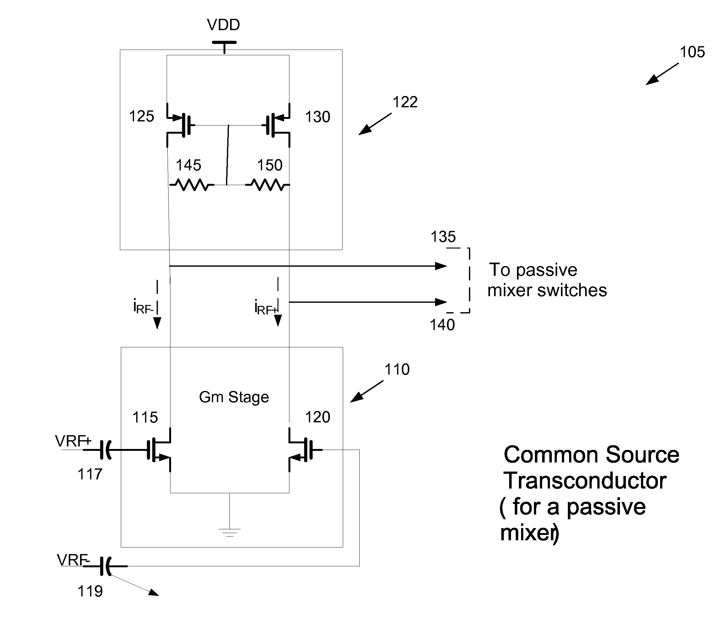
[0012]In another embodiment, the present patent application comprises a method of reducing intermodulation products in a linear transconductor, comprising receiving input signals, amplifying a difference of input signals, converting an input voltage into a current, sensing a nonlinearity in a main current, feed forwarding said nonlinearity, generating an auxiliary current in response to the nonlinearity, cancelling a nonlinear component in the main current by summing said auxiliary current with said main current, whereby intermodulation products are reduced, providing reverse isolation between an input and an output of said linear transconductor, and biasing an active load.

Problems solved by technology

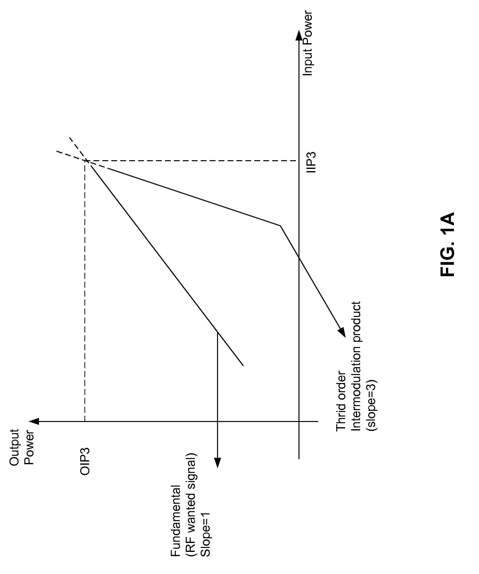
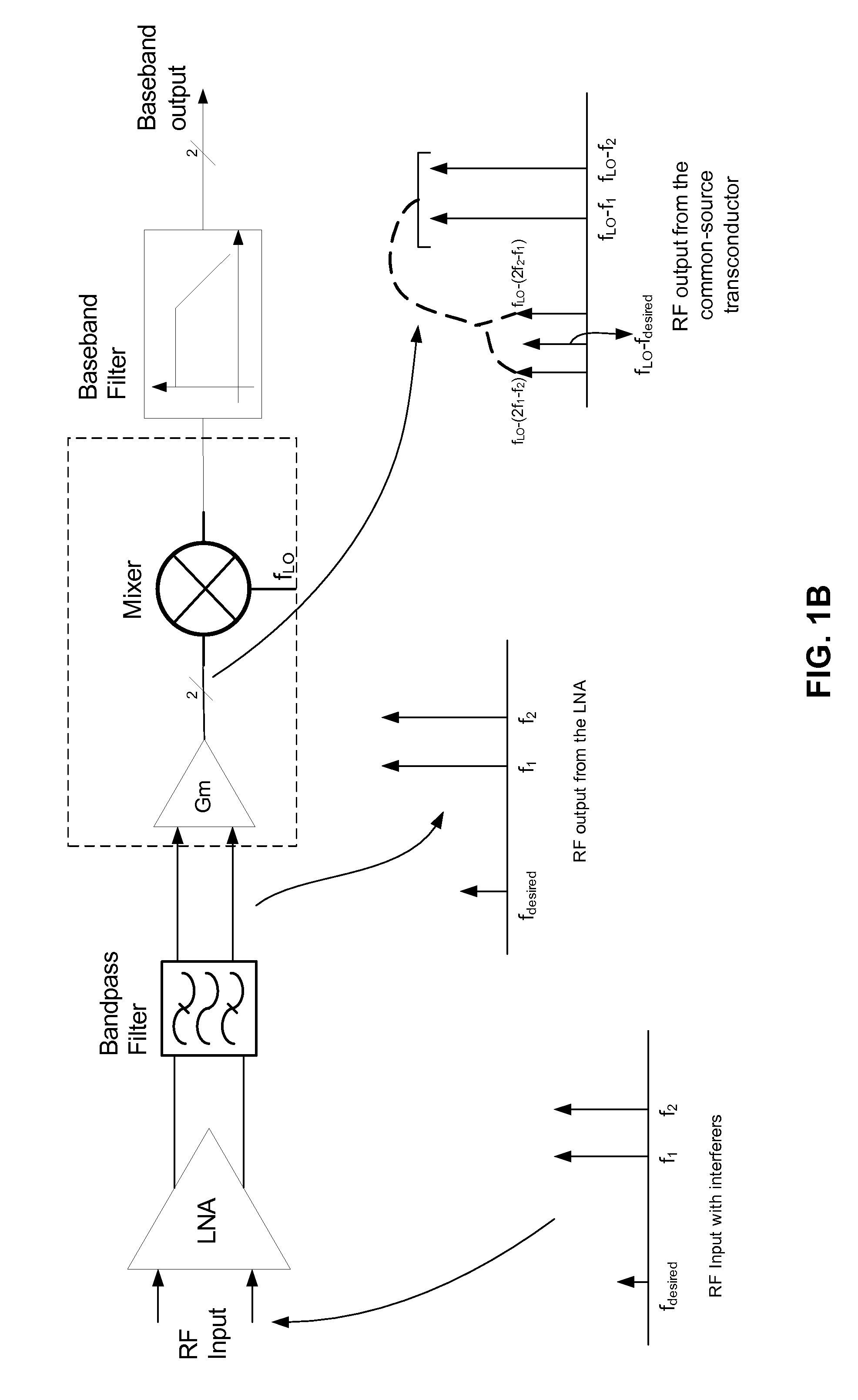
This conversion is nonlinear and, as a result, may produce intermodulation distortion.
Intermodulation distortion is caused by two spurious signals which have a small frequency offset between them, mixing together (due to the nonlinearity of the device characteristics).
The mixer transconductor may be linearized with source degeneration (adding a resistor at the source of the transconductor devices), but this will occur at the expense of increased noise and reduction of gain of the mixer (degradation of noise factor).

Method used


Image

  • Linear transconductor for RF communications
  • Linear transconductor for RF communications
  • Linear transconductor for RF communications

Examples


Embodiment Construction

[0026]The word “exemplary” is used herein to mean “serving as an example, instance, or illustration.” Any embodiment described herein as “exemplary” is not necessarily to be construed as preferred or advantageous over other embodiments.

[0027]The detailed description set forth below in connection with the appended drawings is intended as a description of exemplary embodiments of the present invention and is not intended to represent the only embodiments in which the present invention can be practiced. The term “exemplary” used throughout this description means “serving as an example, instance, or illustration,” and should not necessarily be construed as preferred or advantageous over other embodiments. The detailed description includes specific details for the purpose of providing a thorough understanding of the present invention. However, it will be apparent to those skilled in the art that the present invention may be practiced without these specific details. In some instances, wel...


PUM


Abstract

The present patent application comprises a linear transconductor having at least one input and at least one output, comprising a differential amplifier having a plurality of transistors and a plurality of inputs, wherein a difference of input signals is amplified, a cascode circuit having a plurality of transistors, wherein the transistors are operably connected to the differential amplifier, wherein reverse isolation between an input and an output of the linear transconductor is improved by decoupling the input and the output of the linear transconductor by mounting at least one transistor of the plurality of transistors of the cascode circuit as a common-gate stacked on the at least one transistor of the differential amplifier, an active load having a plurality of transistors operably connected between the cascode circuit and supply voltage, and an auxiliary device operably connected to the connection between the active load, the cascode device and ground.

Description

[0001]This application claims benefit of U.S. Provisional Application No. 60 / 895,659 Titled “Linear Transconductor for a RF Mixer” filed Mar. 19, 2007, the entire disclosure of this application being considered part of the disclosure of this application.BACKGROUND[0002]1. Field of the Invention[0003]The present application pertains to applications where a linear transconductor is required (i.e., a linear voltage to current conversion), and more specifically, a radio frequency (RF) mixer with improved intermodulation product suppression.[0004]2. Background[0005]Mixers are used for up-conversion of baseband (or low frequency) signals and for down-conversion of RF signals. Intermodulation suppression is useful for a RF receiver wherein the mixer serves to downconvert the RF signal to baseband. The mixer stage performs a voltage to current conversion. This conversion is nonlinear and, as a result, may produce intermodulation distortion.[0006]Intermodulation distortion is caused by two s...

Claims


Application Information

Patent Timeline
Patent Type & Authority Applications(United States)
IPC IPC(8): H03F3/45
CPCH03F1/32H03F1/3211H03F3/45H03F3/45188H03F2203/45352H03F2200/357H03F2203/45068H03F2203/45318H03F3/45659
Inventor MUTHALI, HARISHBARNETT, KENNETH CHARLES
Owner QUALCOMM INC
Learn More