
Motor drive apparatus and motor drive method

a technology of motor drive and motor drive, which is applied in the direction of motor/generator/converter stopper, motor/electric converter control, instruments, etc., can solve the problems of motor drive noise increase, disturbance of drive current waveform, and low detection accuracy of overcurrent, so as to reduce current ripples and accurately detect overcurrent , the effect of preventing the rise of power supply voltag

Inactive Publication Date: 2008-09-25
COLLABO INNOVATIONS INC
View PDF16 Cites 30 Cited by
  • Summary
  • Abstract
  • Description
  • Claims
  • Application Information

AI Technical Summary

Benefits of technology

"The present invention provides a motor, a motor drive apparatus, an optical disc apparatus, and a current control method that can accurately detect overcurrent and carry out motor drive control with smooth drive current waveforms while preventing the rising in power supply voltage during current limitation. The invention uses a simple low-cost configuration and can reduce noise during current limitation to improve the performance and reliability of the motor."

Problems solved by technology

In other words, there is a fear that overcurrent detection accuracy lowers depending on the setting of the filtering constant.
As the current ripples increase, disturbances occur in the waveforms of the drive currents.
Consequently, there is a problem that motor drive noise increases owing to the disturbances occurred in the waveforms of the drive currents when the overcurrent protection is performed as described above.
As a result, there is a fear that the power supply voltage is raised by the regenerated currents depending on the capability of the power supply and that the power supply voltage rises to the rated value or more in some cases.
For this reason, in the conventional configuration, there is a fear of degrading or damaging devices, such as the drive transistors, although current limitation is performed.
Furthermore, there is a problem of generating noise owing to the rising in power supply voltage.
Since the operation exiting from the overcurrent protection state is synchronized with the PWM signal, the waveforms of the drive currents during the overcurrent protection operation are susceptible to the PWM frequency.
Furthermore, if the decrease amounts of the currents are large and abrupt current changes occur, this results in a problem of increasing noise.
Consequently, the switching operation for the overcurrent protection is performed within the audible frequency range, and noise becomes larger.
In addition, since the current ripples Ir also become larger, the waveforms of the drive currents are disturbed, and noise becomes larger.
Eventually, there is a problem of increasing noise during the overcurrent protection operation.

Method used


Image

  • Motor drive apparatus and motor drive method
  • Motor drive apparatus and motor drive method
  • Motor drive apparatus and motor drive method

Examples


embodiment 1

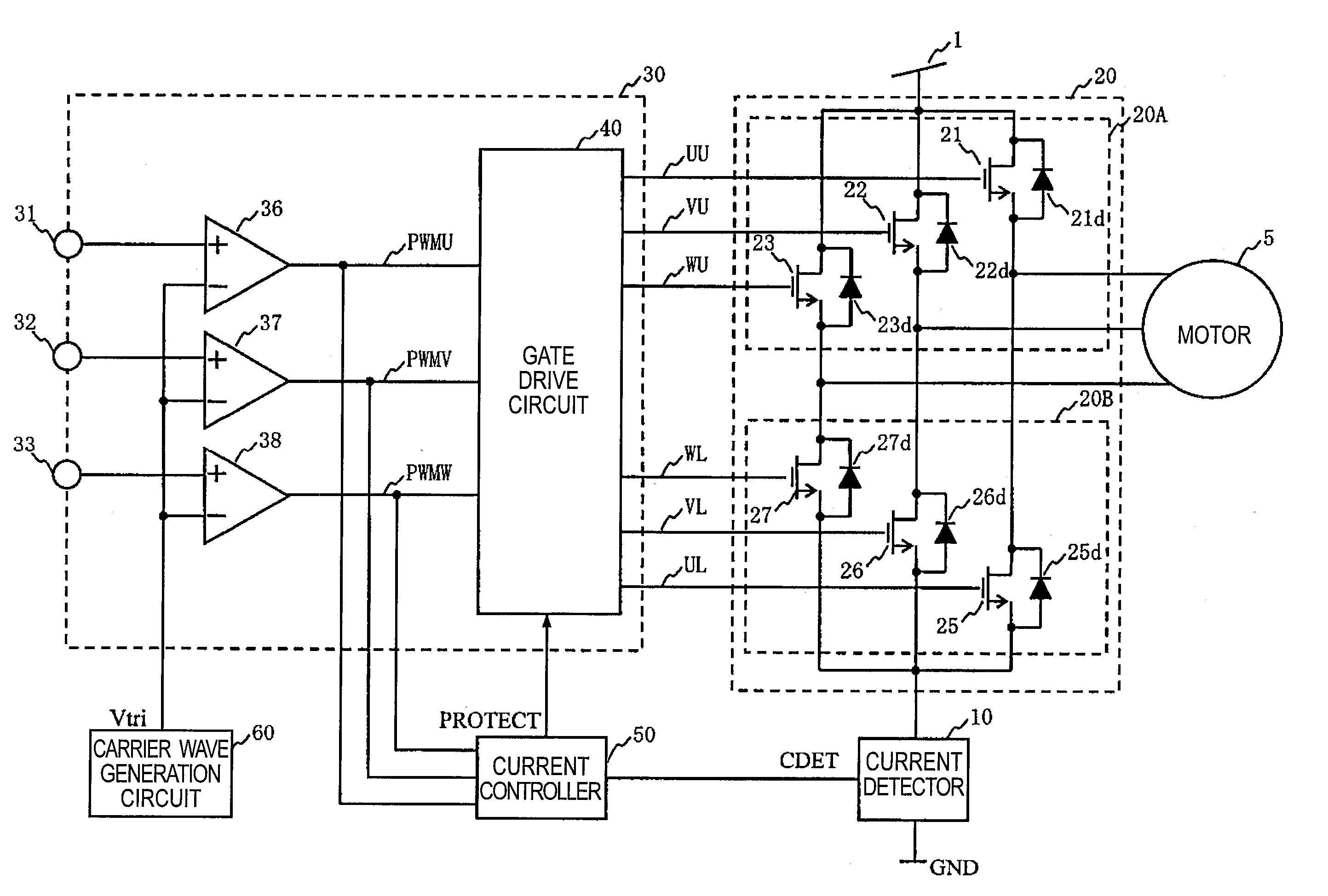
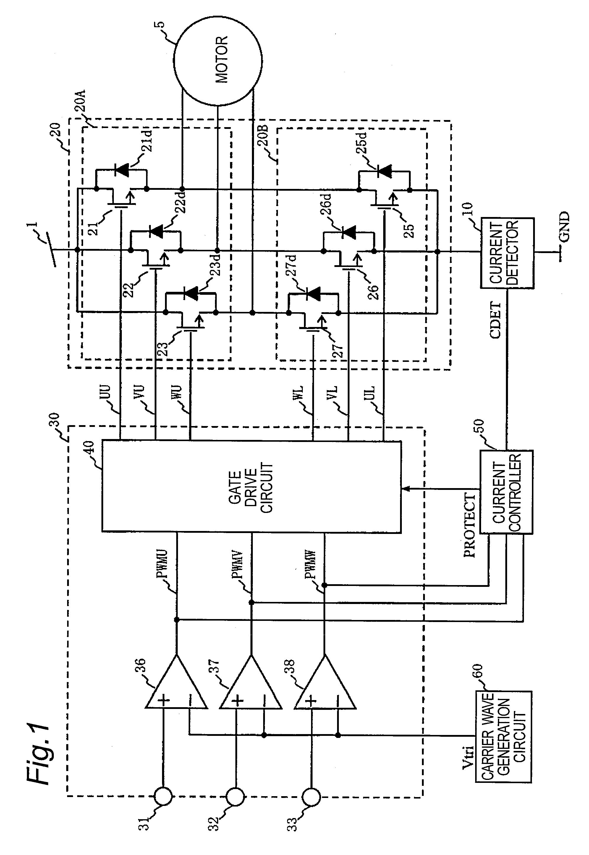
[0082]A motor drive apparatus and a motor drive method according to Embodiment 1 of the present invention will be described referring to FIGS. 1 to 11. FIG. 1 is a view showing the overall configuration of the motor drive apparatus according to Embodiment 1.

[0083]A power supply unit 20 serving as power supply means has a three-phase bridge configuration. One terminal of the power supply unit 20 is connected to a DC power supply 1, and the other terminal thereof is grounded (GND) via a current detector 10. The power supply unit 20 configured as described above carries out switching operation using gate control signals UU, VU, WU, UL, VL and WL coming from a switching controller 30, thereby supplying AC power to a motor 5. The motor 5 comprises a rotor (not shown) having a magnetic field section formed of permanent magnets and a stator (not shown) in which three-phase coils are Y-connected.

[0084]The power supply unit 20 comprises a three-phase high-side drive transistor group 20A cons...

embodiment 2

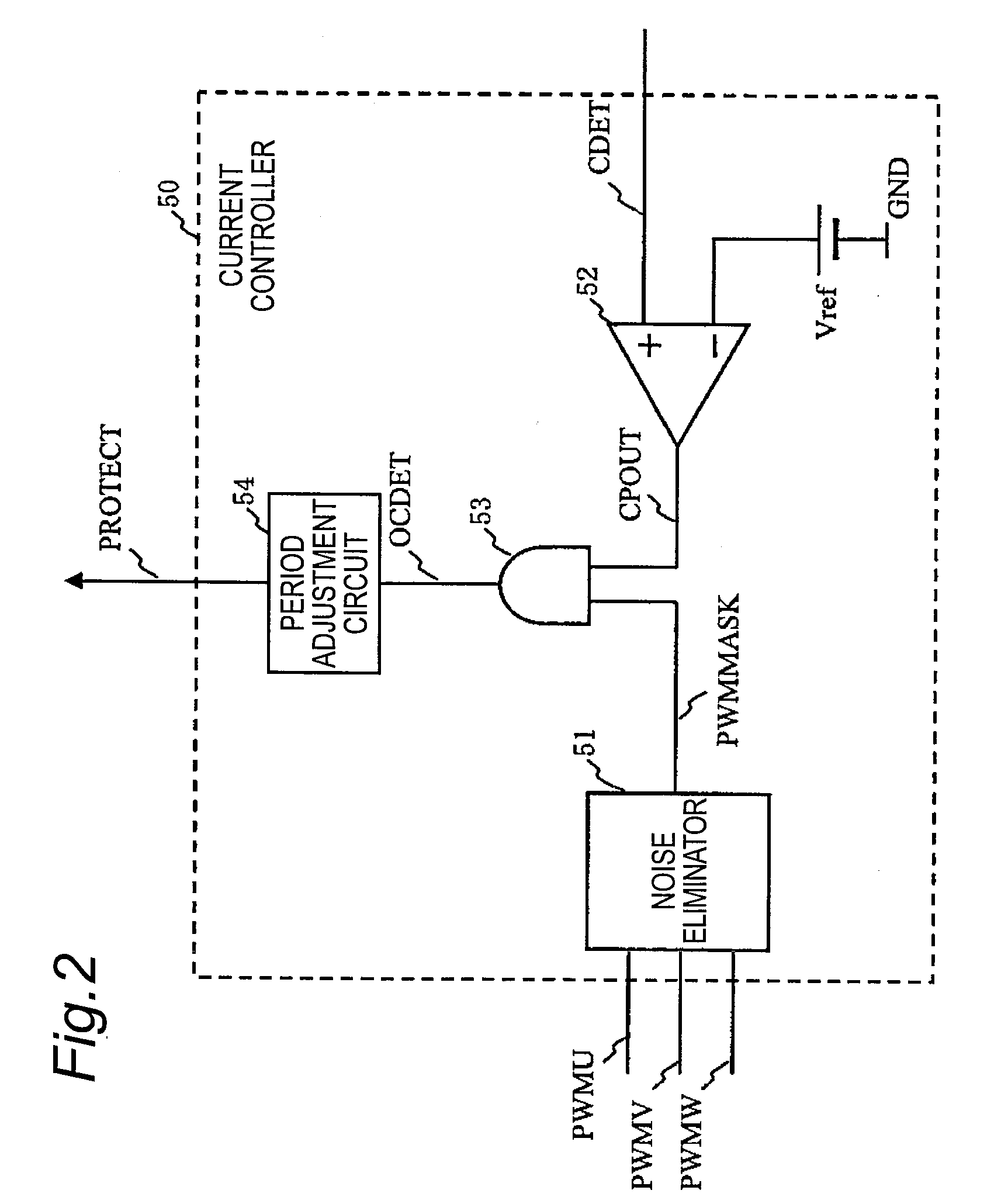
[0123]Next, a motor drive apparatus and a motor drive method according to Embodiment 2 of the present invention will be described referring to FIGS. 12 to 14. FIG. 12 is a view showing the overall configuration of the motor drive apparatus according to Embodiment 2. The motor drive apparatus according to Embodiment 2 differs from the motor drive apparatus according to Embodiment 1 in the configuration of a current controller 50A and in that the U-phase terminal voltage Vu is input to the current controller 50A. Furthermore, although the short-circuit braking operation period during the current limitation according to Embodiment 1 is set to the constant predetermined period Tb, the motor drive apparatus according to Embodiment 2 differs in that the short-circuit braking operation period during the current limitation is variable depending on the detection result of a current decrease amount. Since the other configurations and operations according to Embodiment 2 are the same as those ...


PUM

PropertyMeasurementUnit
frequencyaaaaaaaaaa
frequencyaaaaaaaaaa
frequencyaaaaaaaaaa

Abstract

To reduce noise by limiting a current peak value to a predetermined value or less and by smoothing the waveforms of drive currents during the current limitation, switching control means (30) according to the present invention turns ON all of one-side drive transistors selected from the high-side drive transistors (21, 22 and 23) and the low-side drive transistors (25, 26 and 27) of power supply means (20) for a predetermined period, and turns OFF all of the other-side drive transistors for a predetermined period in response to a current control signal for the current peak value to a predetermined value or less.

Description

BACKGROUND OF THE INVENTION[0001]The present invention relates to a motor drive apparatus and a motor drive method capable of reducing noise by limiting a current peak value to a predetermined value or less and by smoothing the waveforms of drive currents during the current limitation.[0002]FIG. 15 is a view showing the configuration of a conventional motor drive apparatus for providing overcurrent protection. The operation of the conventional motor drive apparatus will be described briefly referring to FIG. 15. A power supply unit 20 carries out switching operation depending on control signals coming from a drive circuit 400 and supplies power from a DC power supply 1 to a motor 5. The current flowing through the power supply unit 20 is detected by measuring the voltage across both terminals of a current detection resistor (shunt resistor) 100.[0003]The current detection signal detected using the current detection resistor 100 is filtered using a filter comprising a resistor 61 and...

Claims


Application Information

Patent Timeline
Patent Type & Authority Applications(United States)
IPC IPC(8): H02P23/00G11B19/28H02P23/07H02P27/06H02P27/08
CPCH02P3/22H02P23/0036H02M2001/0009H02M7/5395H02P27/08H02P23/0004H02M1/0009
Inventor MORI, HIDEAKIYAMAMOTO, YASUNORIEMURA, NORIAKI
Owner COLLABO INNOVATIONS INC
Learn More