Phase Feedback AFM and Control Method Therefor

Inactive Publication Date: 2008-09-25
JEOL LTD
View PDF4 Cites 3 Cited by
  • Summary
  • Abstract
  • Description
  • Claims
  • Application Information

AI Technical Summary

Benefits of technology

[0015]In another embodiment according to the present invention, the amplitude of oscillation of the cantilever is detected. The amplitude of the driving voltage applied to the cantilever is feedback controlled such that the detected amplitude becomes equal to a preset value. Consequently, the amplitude of oscillation of the cantilever is kept constant. Hence, the topography of the sample surface can be imaged at high sensitivity and accurately.

Problems solved by technology

Consequently, there is the problem that the obtained topographic image deviates from the true surface topography by an amount corresponding to the variation in amplitude.

Method used


Image

  • Phase Feedback AFM and Control Method Therefor
  • Phase Feedback AFM and Control Method Therefor
  • Phase Feedback AFM and Control Method Therefor

Examples


Embodiment Construction

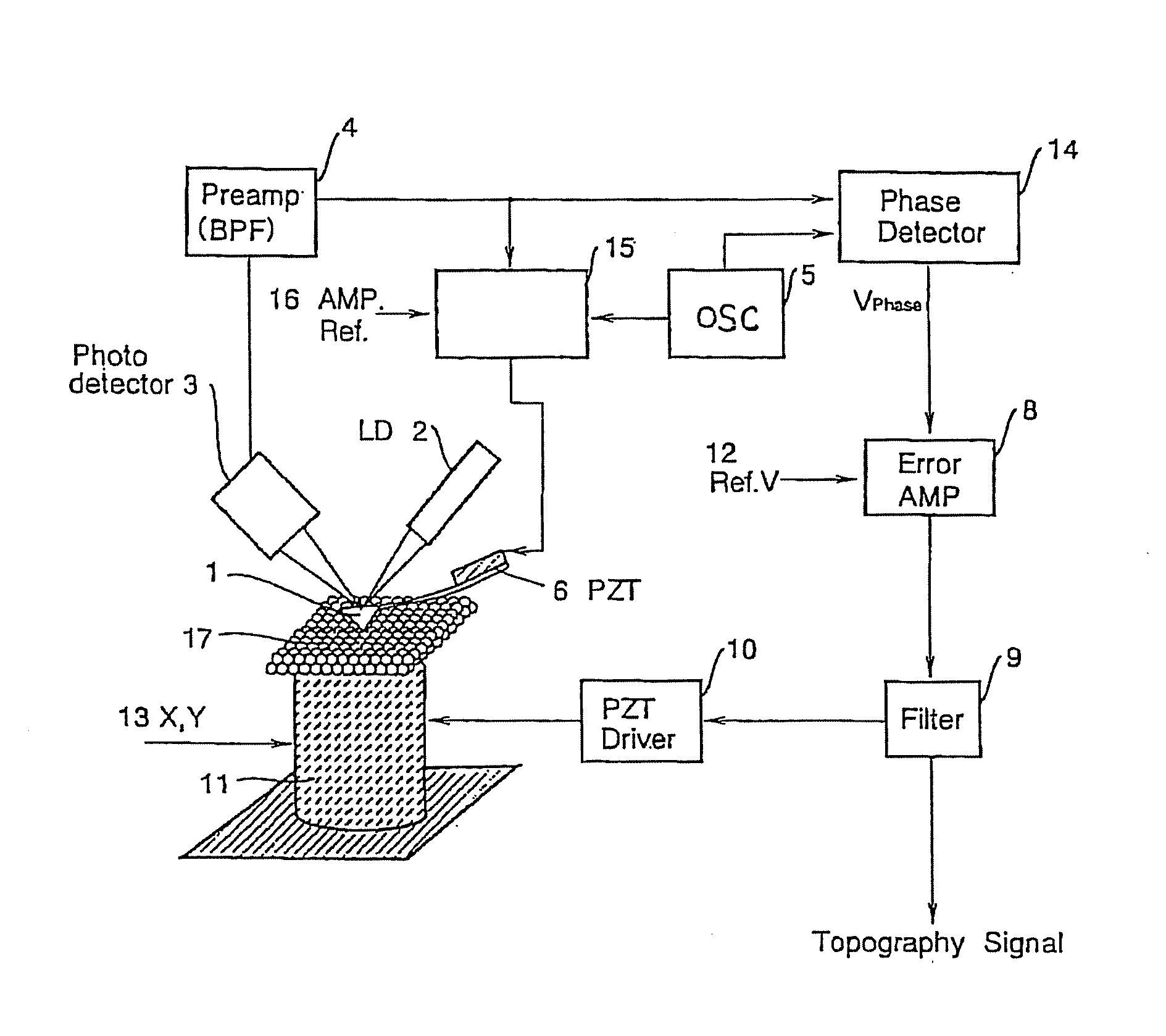
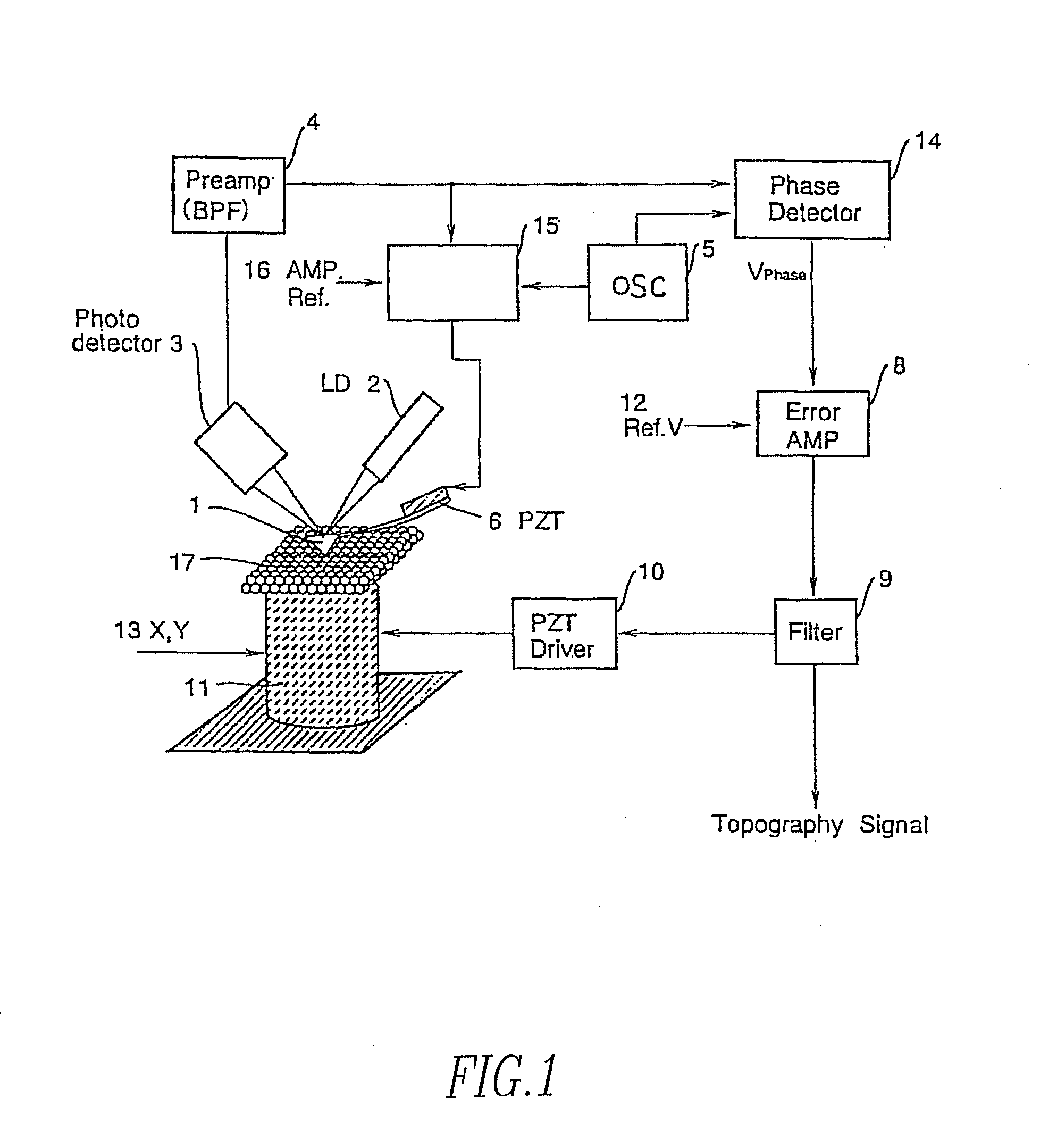
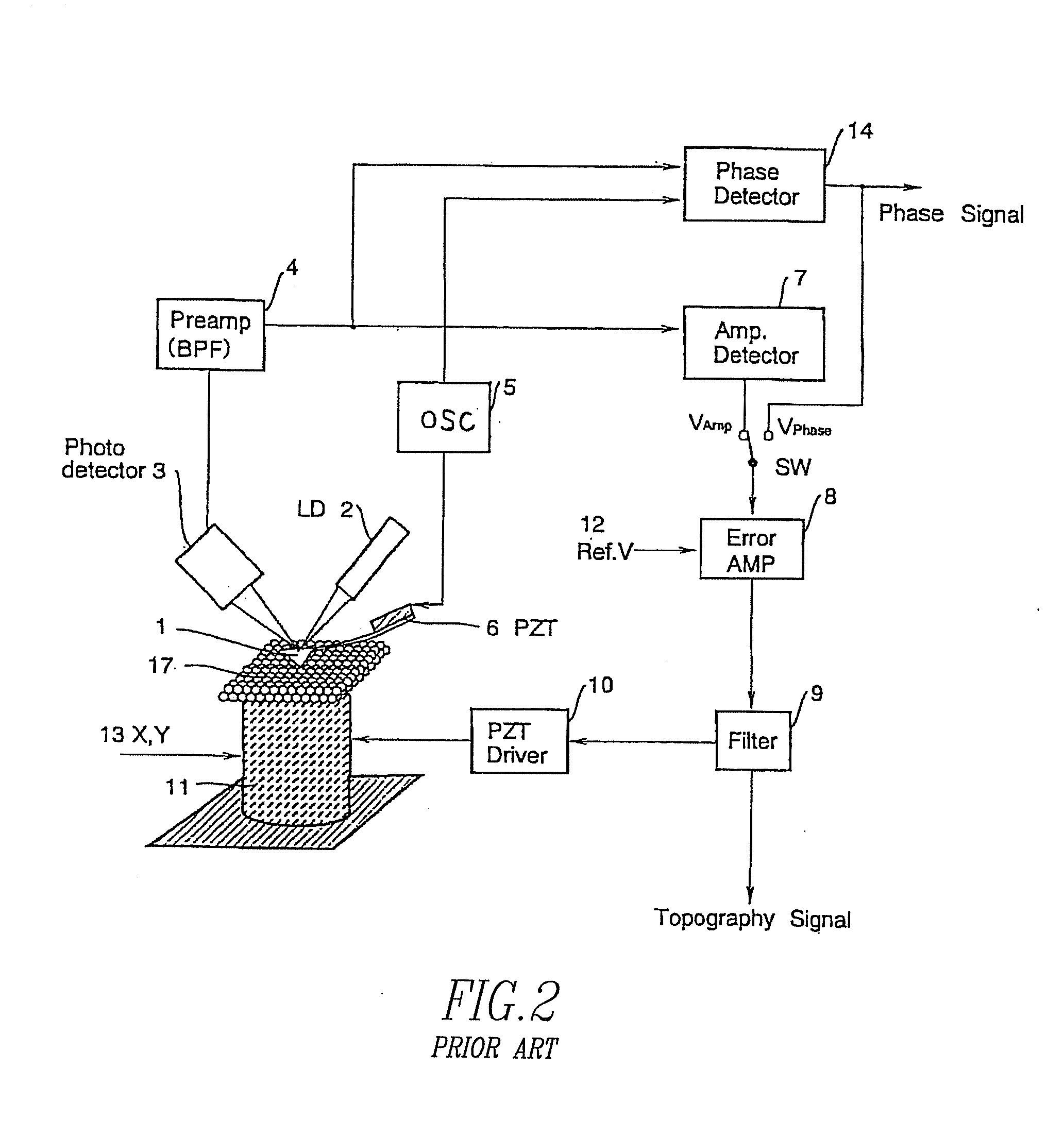
[0019]Embodiments of the present invention are hereinafter described in detail with reference to the drawings. FIG. 1 is a block diagram showing one embodiment of the present invention. In both FIGS. 1 and 2, like components are indicated by like reference numerals. In FIG. 1, a probe (not shown) is attached to the tip of a cantilever 1. The rear surface of the cantilever 1 is irradiated with laser light emitted from a laser diode (LD) 2. Modulated laser light is reflected from the cantilever 1 and hits a photodetector 3, where the light is converted into an electrical signal. The probe is placed over a sample 17. A piezoelectric ceramic transducer (PZT) 6 drives the cantilever 1 which is attached to the PZT 6.

[0020]A preamplifier 4 has a bandpass filter (BPF) function for receiving and amplifying the output from the photodetector 3. Indicated by reference numeral 5 is an oscillator. A phase detector 14 has two input terminals. The output from the preamplifier 4 is applied to one of...


PUM


Abstract

A phase feedback AFM (atomic force microscope) and method for the phase feedback AFM. A cantilever is driven to oscillate at a constant frequency close to the resonance frequency of the cantilever by a driving signal. The distance between the probe and the sample is controlled such that the phase difference between the driving signal and a cantilever deflection signal indicating deflections of the cantilever is kept constant. The phase feedback AFM has an amplifier-controller for receiving the cantilever deflection signal, the output from an oscillator for driving the cantilever into oscillation, and a signal representing a reference amplitude of oscillation of the cantilever. The phase feedback AFM further includes a feedback circuit which receives the output from the amplifier-controller which controls the cantilever deflection signal to a preset amplitude.

Description

BACKGROUND OF THE INVENTION[0001]1. Field of the Invention[0002]The present invention relates to a phase feedback AFM (atomic force microscope) and to a control method for the phase feedback AFM. More particularly, the invention relates to a phase feedback AFM capable of maintaining constant the amplitude of the cantilever oscillation by controlling the amplitude of a driving voltage and to a control method for this phase feedback AFM.[0003]2. Description of Related Art[0004]A scanning probe microscope (SPM) is an instrument for imaging the surface of a sample by scanning a probe relative to the sample while the sample is placed close to the probe, producing a local stimulus from the probe to the sample during the scanning, and measuring a local response of the surface of the sample to the stimulus. Many types of SPM, which are different in method of measuring physical amounts, have been put into practical use. The family of scanning probe microscopy (SPM) includes scanning tunnelin...

Claims


Application Information

Patent Timeline
IPC IPC(8): G01B5/28G01Q60/32
CPCB82Y35/00G01Q10/065G01Q60/32
Inventor KITAMURA, SHINICHI
Owner JEOL LTD
Why Eureka
Try Eureka