
Ethernet Link Monitoring Channel

a monitoring channel and ethernet technology, applied in the field of ethernet communication networks, can solve the problems of increasing the possibility of malfunction, lack of overhead features which may be desirable, and difficulty in providing access to the packet stream for the insertion of link related messages at the link end

Inactive Publication Date: 2008-09-18
QUALCOMM INC
View PDF18 Cites 16 Cited by
  • Summary
  • Abstract
  • Description
  • Claims
  • Application Information

AI Technical Summary

Benefits of technology

This solution enables exhaustive bit error rate measurements and efficient transmission of link monitoring data without affecting user data bandwidth, enhancing the suitability of 10GBASE-R links in optical networks by providing comprehensive link supervision features compatible with the 10GBASE-R standard.

Problems solved by technology

Ethernet on the other hand, having originally been developed as a LAN medium (and having evolved in speed to 10 Gb / s, and in scope to MAN), lacks some overhead features which may be desirable when used directly to interconnect nodes in a MAN environment.
This practice has a number of undesirable consequences: packet bandwidth that is used in carrying link related data is not available as user packet bandwidth; user packets and link related packets are distinguished only through their packet headers, increasing the possibility of malfunctions caused by incorrect headers, malicious packets, or decoding errors; and it may be difficult to provide access to the packet stream for the insertion of link related messages at link ends, for example requiring extra buffers and causing unwanted delay.
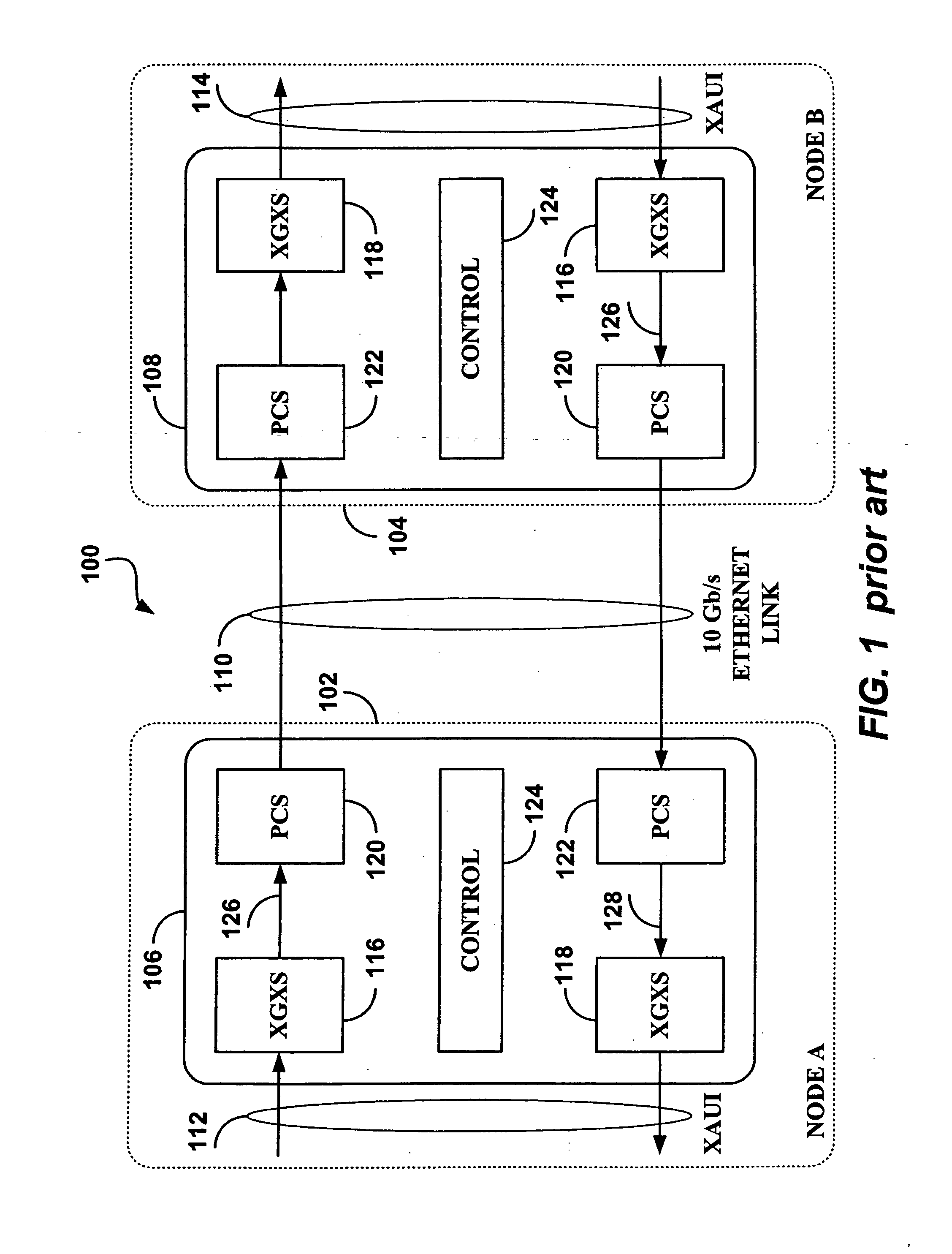
While providing a standard (the MDIO) and other means (DOM) for the local monitoring of module and link performance, the 10GBASE-R standard, in the interest of keeping the cost of such links at a minimum, does not provide capabilities for transmitting link related information directly to the other end of the link.
This capability is intended to report a condition indicating an inability of the node to communicate, and is not suitable for link monitoring.

Method used


Image

  • Ethernet Link Monitoring Channel
  • Ethernet Link Monitoring Channel
  • Ethernet Link Monitoring Channel

Examples


Embodiment Construction

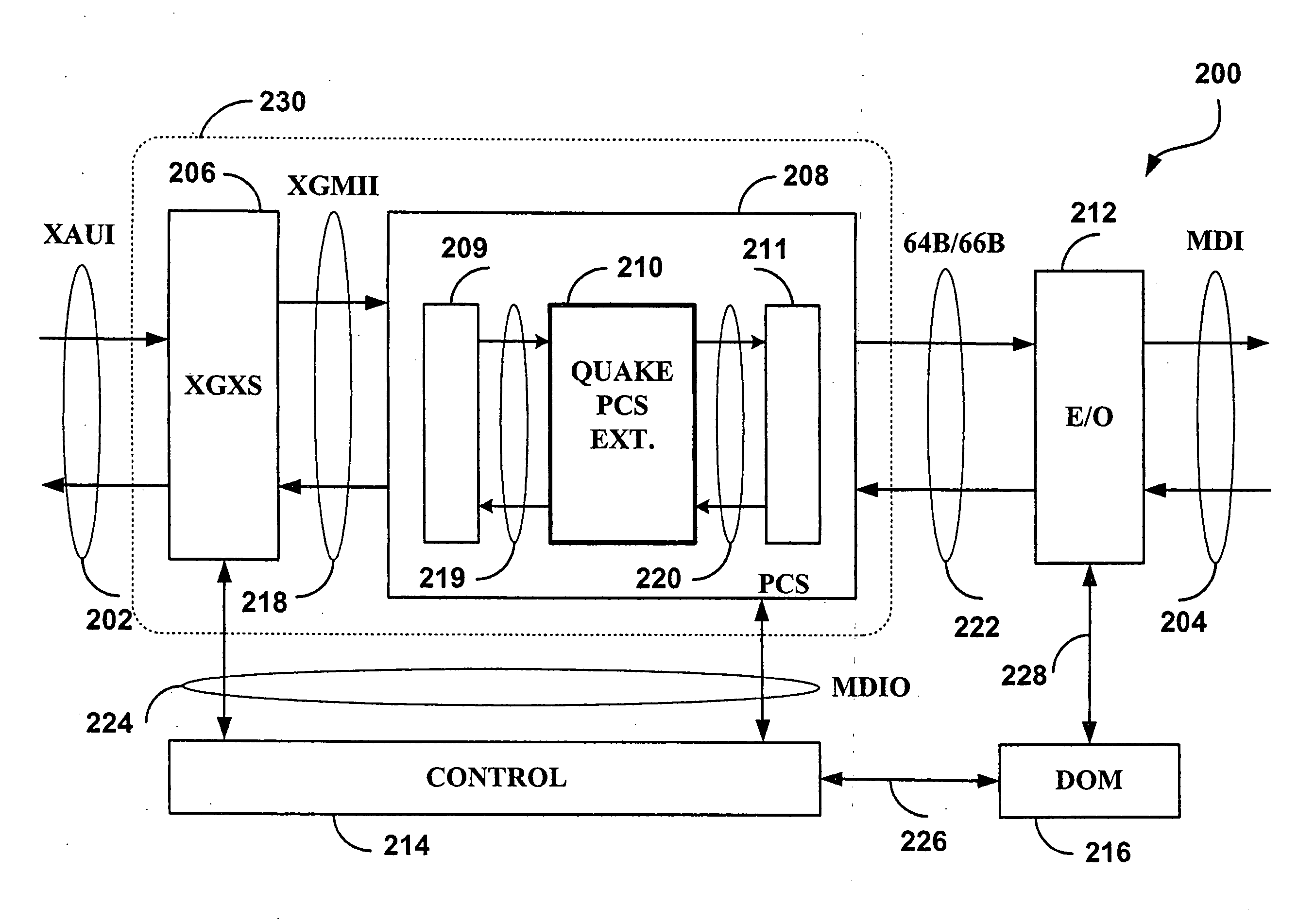
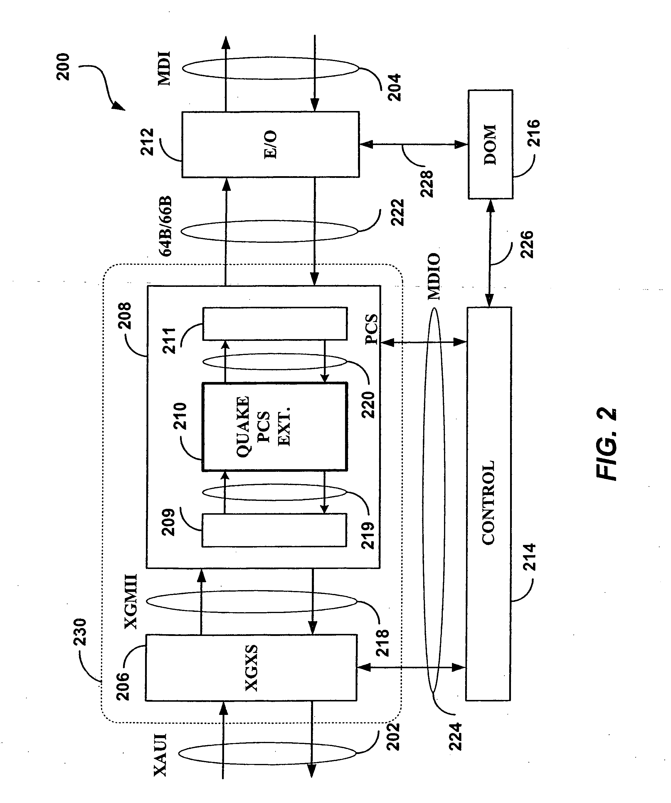
[0059]An Extended Link Monitoring Channel has been developed to be incorporated in a 10GBASE-R link providing the capability to transmit information in addition to, and without affecting, the carriage of user data packets. The Extended Link Monitoring Channel can be used to conduct exhaustive BER measurements over the link, transmit the results of Digital Optical Monitoring (DOM), or any other information. The Extended L,ink Monitoring Channel requires enhancements to the transceiver for 10GBASE-R, an initialization procedure to set up the channel, and a transfer protocol for the use of the channel.

[0060]Transceiver

[0061]A transceiver 200 for an improved 10GBASE-R link having means for implementing an Extended Link Monitoring Channel according to an embodiment of the invention, is shown in FIG. 2.

[0062]The transceiver 200 comprises a number of modules operating in both the transmit direction and the receive direction between an electrical “10 Gigabit Attachment Unit Interface” (XAUI...


PUM


Abstract

The invention provides a method for utilizing the Inter Packet Gaps (IPGs) to create an Extended Link Monitoring Channel in a physical layer transceiver for a 10 Gb / s Ethernet link for communicating link related information, thus providing an extensive link maintenance capability. A corresponding transceiver between an Ethernet media access control (MAC) layer device and a 10 Gb / s Ethernet link, comprising a physical coding sublayer (PCS) extension circuit for implementing the Extended Link Monitoring Channel is also provided.

Description

RELATED APPLICATIONS[0001]This application is a Continuation of a pending application entitled, AN EXTENDED LINK MONITORING CHANNEL FOR 10 Gb / s ETHERNET, invented by Popescu et al., Ser. No. 10 / 701,485, filed Nov. 6, 2003, which is incorporated herein by reference.FIELD OF THE INVENTION[0002]The invention related to Ethernet communications networks, and in particular, to an extended link monitoring channel for 10 Gb / s Ethernet.BACKGROUND OF THE INVENTION[0003]The Ethernet Standard (IEEE 802.3) has recently been extended to include optical communications links operating at the speed of 10 Gb / s (IEEE Draft P802.3ae 2002). In this application, the IEEE 802.3 standard with its supplements will simply be referred to as the standard, and will be incorporated herein by reference.[0004]For communication links in Local Area Network (LAN) and Metropolitan Area Network (MAN) environments, the new type of links (also known as 10GBASE) provides a lower cost alternative to SONET OC192 which has t...

Claims


Application Information

Patent Timeline
Patent Type & Authority Applications(United States)
IPC IPC(8): G06F15/173H04L12/24H04L12/26
CPCH04L12/2602H04L43/0811H04L43/00
Inventor POPESCU, PETRETREPANIER, DANIEL PIERREWOLSKI, STANISLASMATHUR, NIRAJ RAJENDRA
Owner QUALCOMM INC
Learn More