
Robot

a robot and actuator technology, applied in the field of robots, can solve the problems of large load of the actuator for activating the head part, remarkably restricted degree of design freedom, and difficulty in measuring the distance from a work object or a surrounding object, so as to reduce the torque of the actuator for the neck, reduce the torque of the actuator, and simplify the effect of the neck structur

Active Publication Date: 2008-09-18
HITACHI LTD
View PDF2 Cites 15 Cited by
  • Summary
  • Abstract
  • Description
  • Claims
  • Application Information

AI Technical Summary

Benefits of technology

[0008]An object of the present invention is, in view of the above prior art as described above, to provide a robot having simple structure and further, reducing the load of an actuator of a neck part.
[0010]According to the present invention, it is possible to achieve natural appearance, reduction in torque of a neck actuator, expression by various movements of a head part, and simplification of the neck structure, without narrowing a scan field of a surrounding object distance measurement means, e.g. a laser scanning range sensor.

Problems solved by technology

However, in the case of the conventional structure in which a surrounding object distance measurement means, e.g. a laser scanning range sensor, is attached to the top of a head part of a robot as described above, since the head part on which the laser scanning range sensor is mounted is driven by an actuator, the load of the actuator for activating the head part becomes large.
Further, in the case of mounting the laser scanning range sensor on the head part, the head part is shaped so as not to obstruct a laser scanning plane, and therefore the degree of freedom of design has been remarkably restricted.
Furthermore, if the laser scanning range sensor is attached to a front part of a body or a chest part as disclosed in JP-A-2005-125457, shielding occurs with high frequency during operation by an arm, which makes it difficult to measure the distance from a work object or a surrounding object.

Method used


Image

  • Robot
  • Robot
  • Robot

Examples


Embodiment Construction

[0018]Hereinafter, an embodiment of the present invention will be described with reference to the drawings.

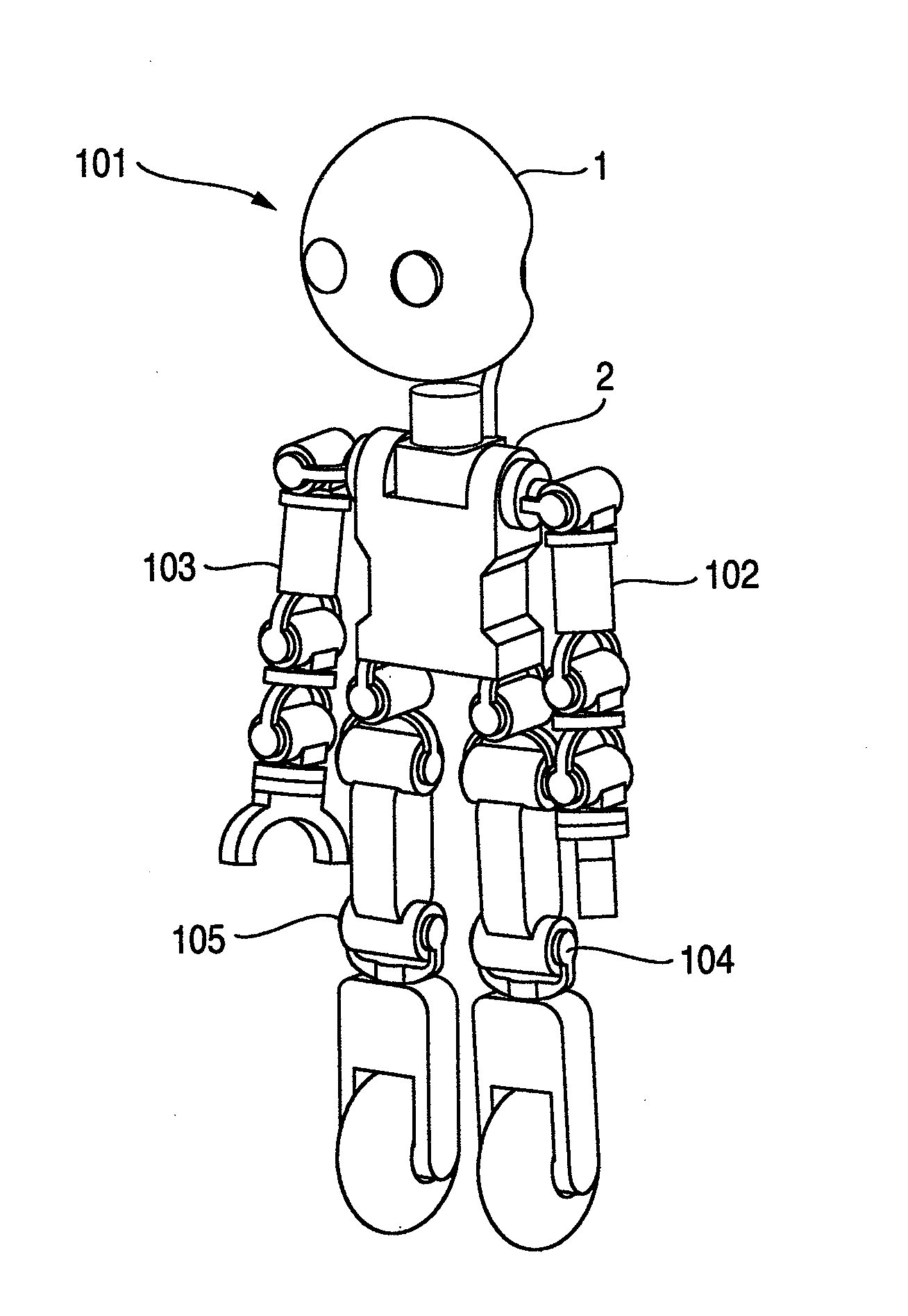
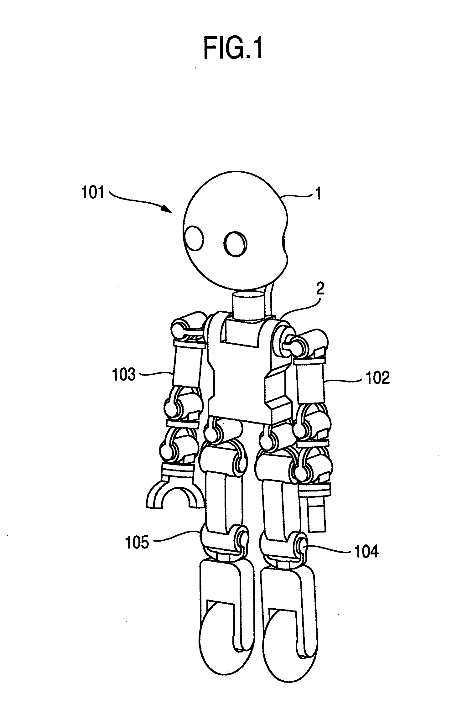
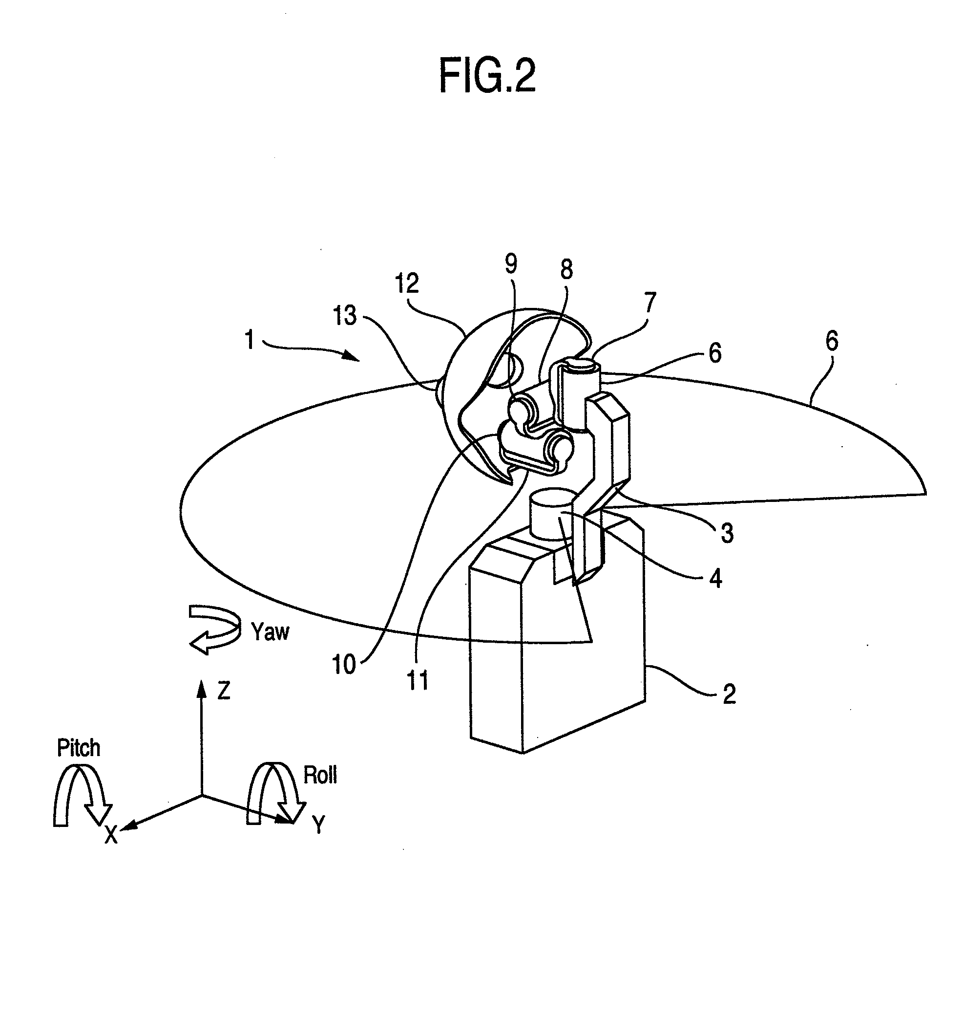
[0019]FIG. 1 is a view showing the whole of a robot of an embodiment, FIG. 2 is a view showing the whole of a head part of the robot of the embodiment, FIGS. 3 and 4 are views showing other configurations, FIG. 5 is a view for explaining movement of a pitch axis of the robot of the embodiment, and FIG. 6 is a view for explaining movement of a roll axis of the robot of the embodiment.

[0020]In the following embodiment, a surrounding object distance measurement means will be described using a laser scanning range sensor as an example. In addition, there is a humanoid robot as an example of a robot to which the present invention is applied, and the description is made using it as an example.

[0021]A robot 101 is composed of a head part 1, a body part 2, a left arm 102, a right arm 103, a left leg 104 and a right leg 105. For example, the left leg 104 and the right leg 105 are used f...


PUM


Abstract

To provide a robot whose degree of freedom of design is not limited, and which has simple structure and further reduces load of an actuator of a neck part, the present invention provides a robot at least including a head part, a body part, and a neck link which connects the head part and the body part, wherein a surrounding object distance measurement means is provided adjacently to the neck link and in an upper portion of the body part between the head part and the body part, and a distance scanning field of the surrounding object distance measurement means is provided in parallel with a horizontal plane.

Description

BACKGROUND OF THE INVENTION[0001]1. Field of the Invention[0002]The present invention relates particularly to a robot provided with a surrounding object distance measurement means to automatically perform desired operation or work while measuring the distance from a work object and an obstacle.[0003]2. Description of Related Art[0004]In many cases, a robot which operates in a coexistence environment with a human is provided with a surrounding object distance measurement means to avoid contact with a surrounding object, and thereby recognizes disposition conditions of the surrounding objects to set a moving route. As one example of the surrounding object distance measurement means, there is a laser scanning range sensor (SOKUIKI sensor) which determines the distance by measuring the time elapsed after a plane is scanned with laser light until the irradiated laser light hits against an object to be measured and the reflected light returns, and in order to widen a scan field, the laser...

Claims


Application Information

Patent Timeline
Patent Type & Authority Applications(United States)
IPC IPC(8): B25J19/02B25J19/04B25J11/00
CPCG01S17/88B25J19/022B25J17/00
Inventor AMINO, AZUSATAMAMOTO, JUNICHINAKAMURA, RYOSUKE
Owner HITACHI LTD
Learn More