
Axle housing with differential bearing support

Inactive Publication Date: 2008-09-18
DANA AUTOMOTIVE SYST GRP LLC
View PDF11 Cites 18 Cited by
  • Summary
  • Abstract
  • Description
  • Claims
  • Application Information

AI Technical Summary

Benefits of technology

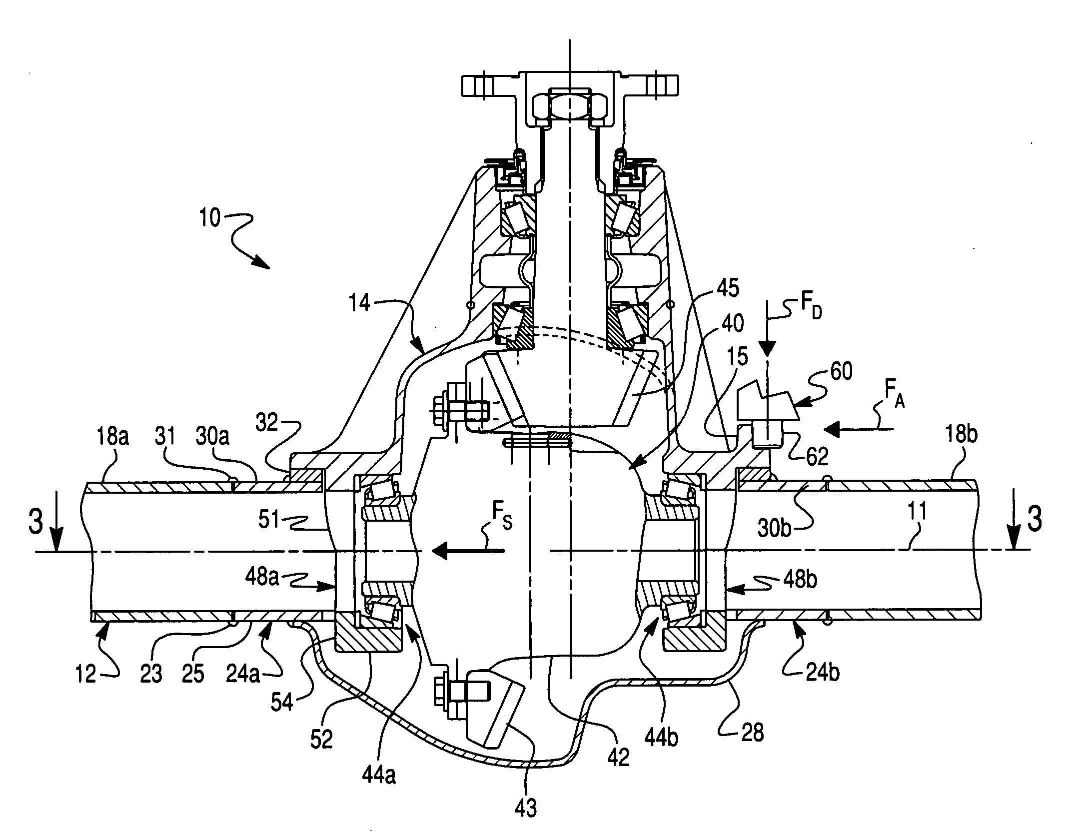
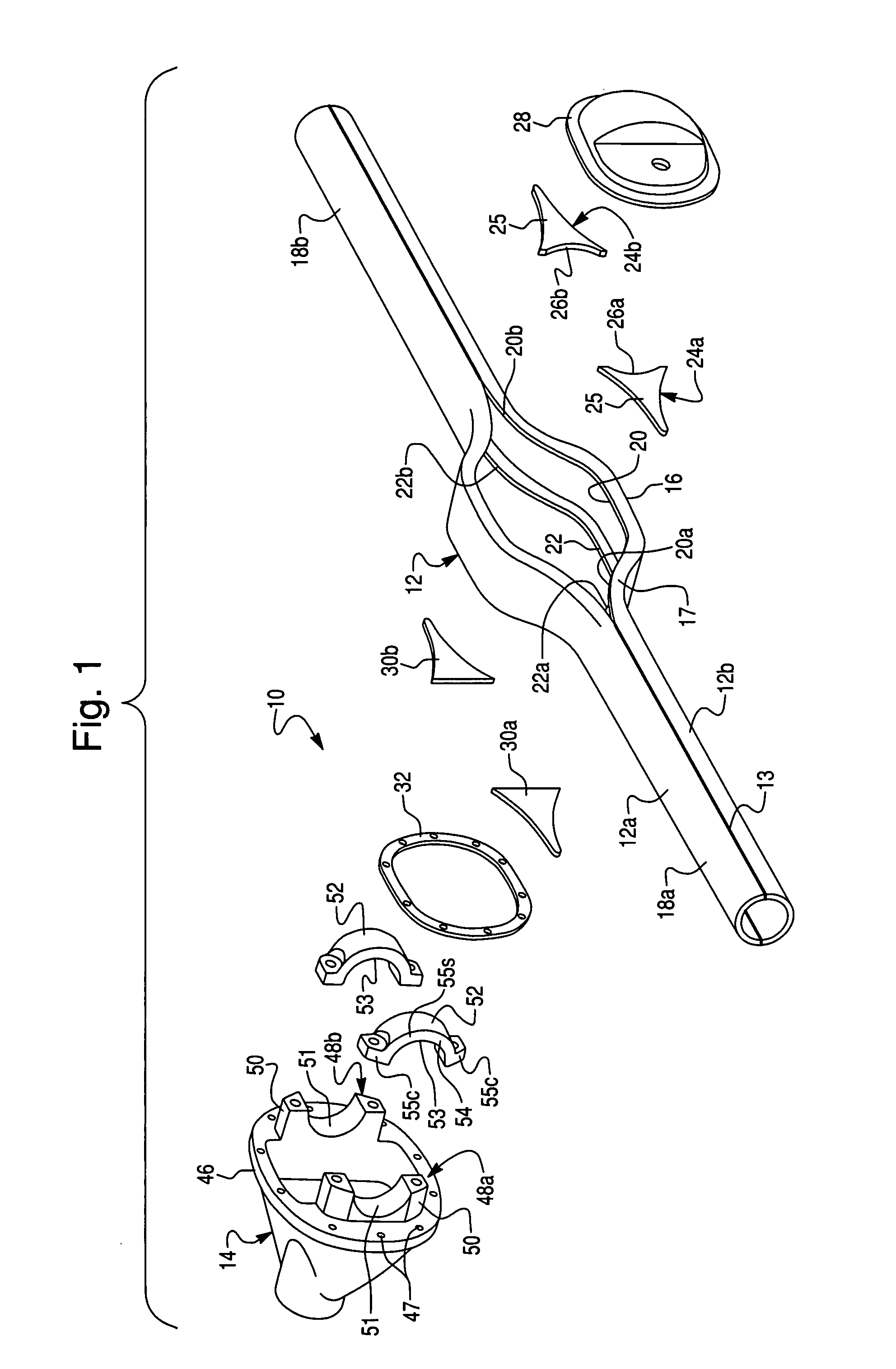
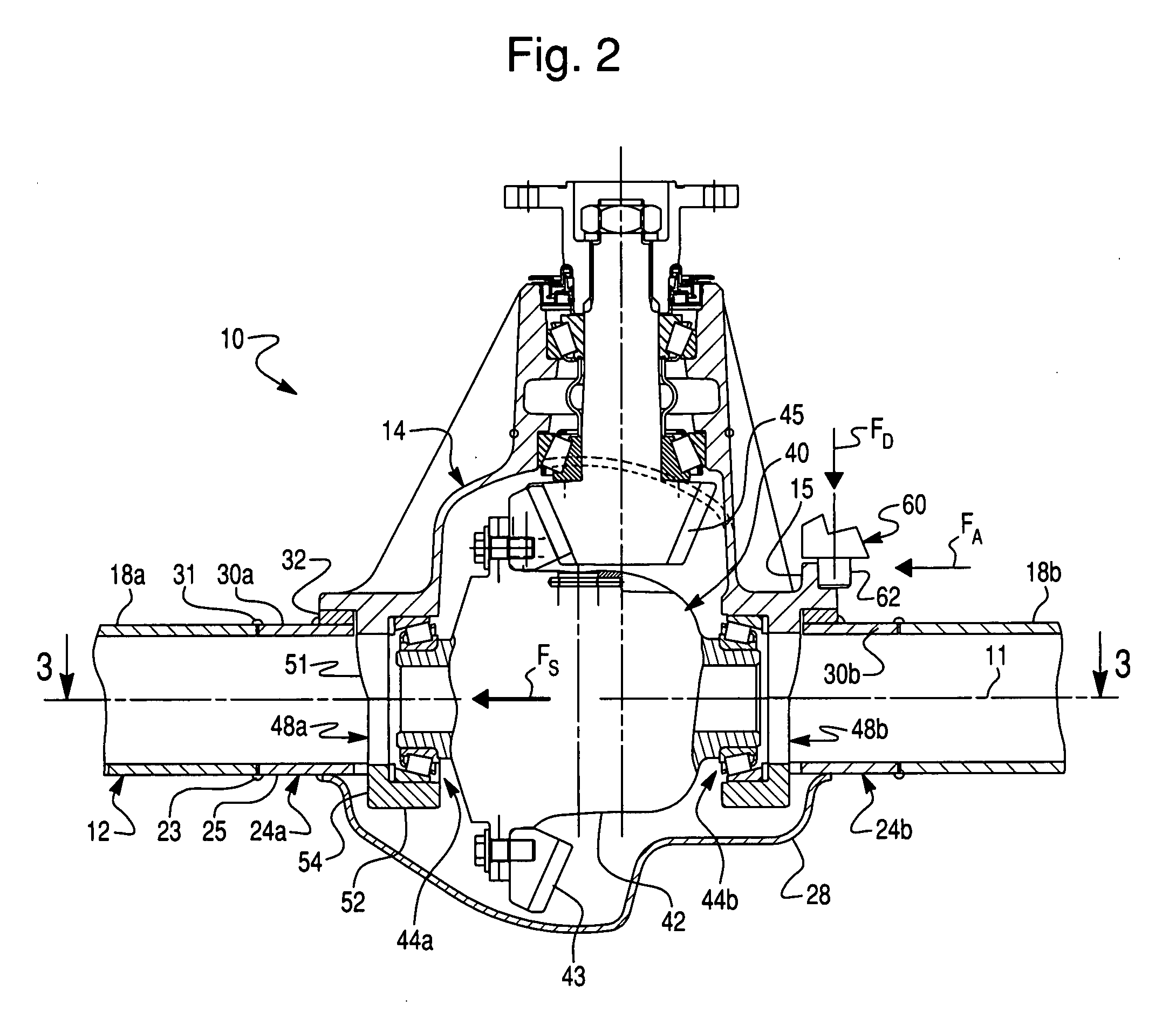
[0012]Therefore, the present invention provides a novel abutment structure for a differential bearing support in the form of an abutment member attached to an axle housing and oriented in a direction of a gear separating force imparted in operation on the differential so as to engage the bearing support and absorb the gear separating force. Thus, the present invention minimizes or prevents (restraints) deflections of the bearing support and, therefore, holds differential gears in proper positions, and extends the useful life and strength of the axle assembly. The present invention provides an economical means to support the differential bearing support to resist movement while under load.

Problems solved by technology

The gear separating force can be large enough to deflect the bearing supports, causing undesirable misalignment of differential gears and consequent premature wear.
This decreases the torque capacity and life of hypoid gear sets (final drive) in banjo-type axle assemblies.
With known carrier structures, the size of the bearing supports is limited by the available space within the opening of the central section.
As a result of a clearance necessary to assemble the carrier into the banjo housing, the bearing cap does not have any structural support to resist the deflection of the bearing support under load.
In other words, currently banjo-type axle housings do not support the differential bearing caps.
Thus, the banjo-type axle housings of the prior art are susceptible to improvements that reduces premature wear of a differential and extends the useful life of the axle assembly.

Method used


Image

  • Axle housing with differential bearing support
  • Axle housing with differential bearing support
  • Axle housing with differential bearing support

Examples


Embodiment Construction

[0022]The preferred embodiments of the present invention will now be described with the reference to accompanying drawing.

[0023]For purposes of the following description, certain terminology is used in the following description for convenience only and is not limiting. The words such as “front” and “rear”, “left” and “right”, “inboard” and “outboard”, “inwardly” and “outwardly” designate directions in the drawings to which reference is made. The words “smaller” and “larger” refer to relative size of elements of the apparatus of the present invention and designated portions thereof. The terminology includes the words specifically mentioned above, derivatives thereof and words of similar import. Additionally, the word “a”, as used in the claims, means “at least one”.

[0024]Referring to FIG. 1 of the drawings, a first exemplary embodiment of a drive axle assembly, generally denoted by reference numeral 10, for use in a conventional motor vehicle, is illustrated. The axle assembly 10 inc...


PUM


Abstract

An axle assembly for a motor vehicle comprises an axle housing having a central axis and first and second openings formed through the axle housing opposite to each other, a carrier with a differential bearing support supporting a differential thereon for rotation about the central axis, and an abutment member attached to the axle housing adjacent to the first opening to extend substantially in a direction of the central axis. The carrier is fastened to the axle housing adjacent to the second opening therein. The abutment member engages the differential bearing support and absorbs a gear separating force imparted in operation by the differential and transmitted to the differential bearing support. Thus, the abutment member restrains deflection of the differential bearing support relative to the axle housing resulting from the gear separating force.

Description

BACKGROUND OF THE INVENTION[0001]1. Field of the Invention[0002]This invention relates in general to vehicle axle assemblies and in particular to an axle housing provided for restraining an axial deflection of a differential bearing support.[0003]2. Description of the Prior Art[0004]Axle assemblies are well known structures which are in common use in many motor vehicles. Such axle assemblies include a number of components which are adapted to transmit rotational power from an engine of the vehicle to drive wheels thereof. Typically., an axle assembly comprises a differential mounted to a non-rotating carrier. The differential, in turn, includes a differential mechanism disposed in a differential case which is rotatably supported within the non-rotating carrier. The differential is connected between an input drive shaft extending from the vehicle engine and a pair of output axle shafts extending to the vehicle drive wheels. The axle shafts are contained in respective non-rotating hol...

Claims


Application Information

Patent Timeline
IPC IPC(8): F16H48/06F16H57/02
CPCB60B35/16B60B35/18B60B2310/206B60B2310/228B60B2310/302B60B2310/305Y10T74/2186B60B2380/14F16H48/06F16H57/037F16H2057/02052F16H2057/02091F16H2057/0213B60B2360/147
Inventor CATALANO, MICHAEL J.KRISHER, JAMES A.NAHRWOLD, THOMAS L.
Owner DANA AUTOMOTIVE SYST GRP LLC
Learn More