
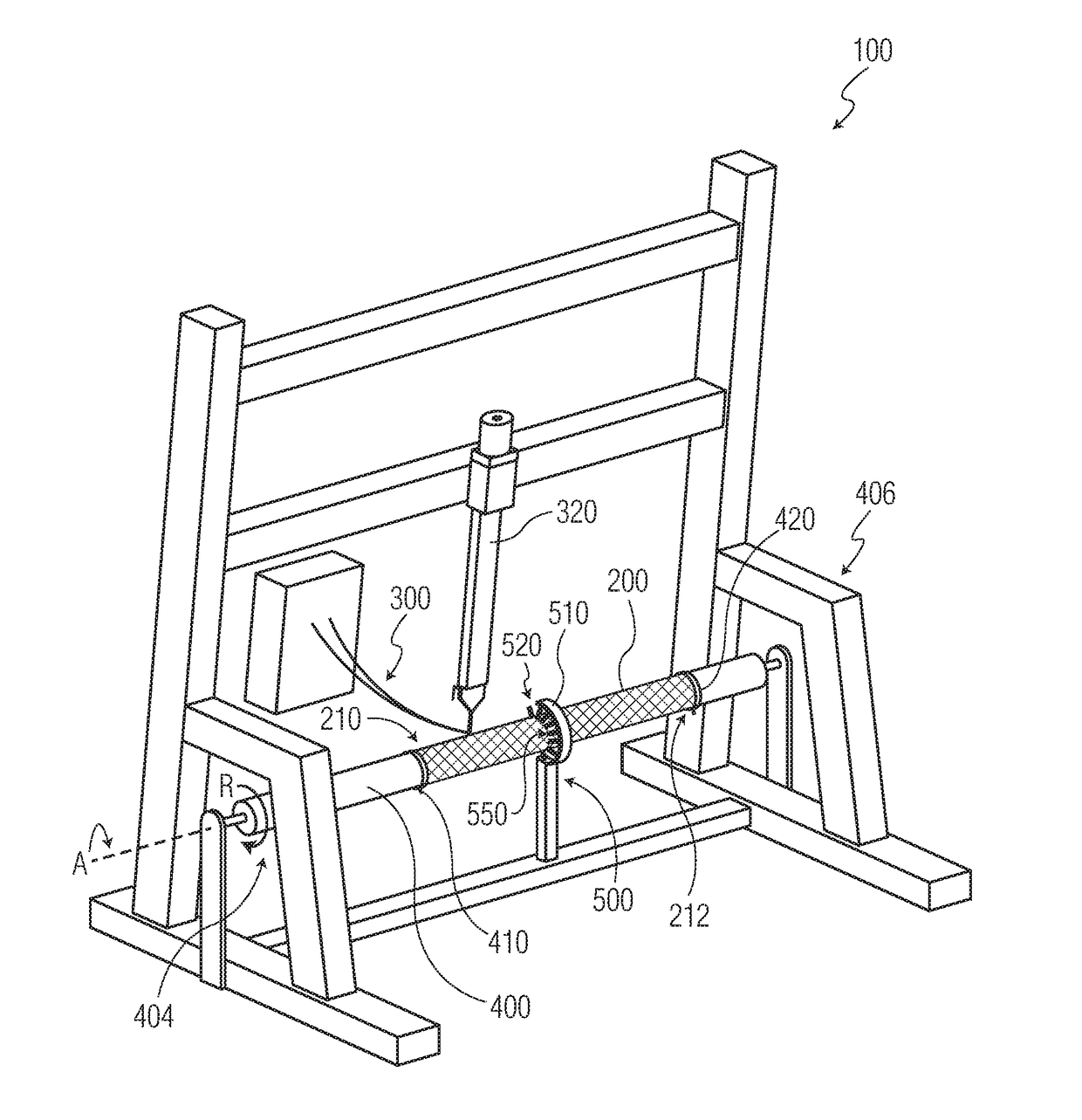
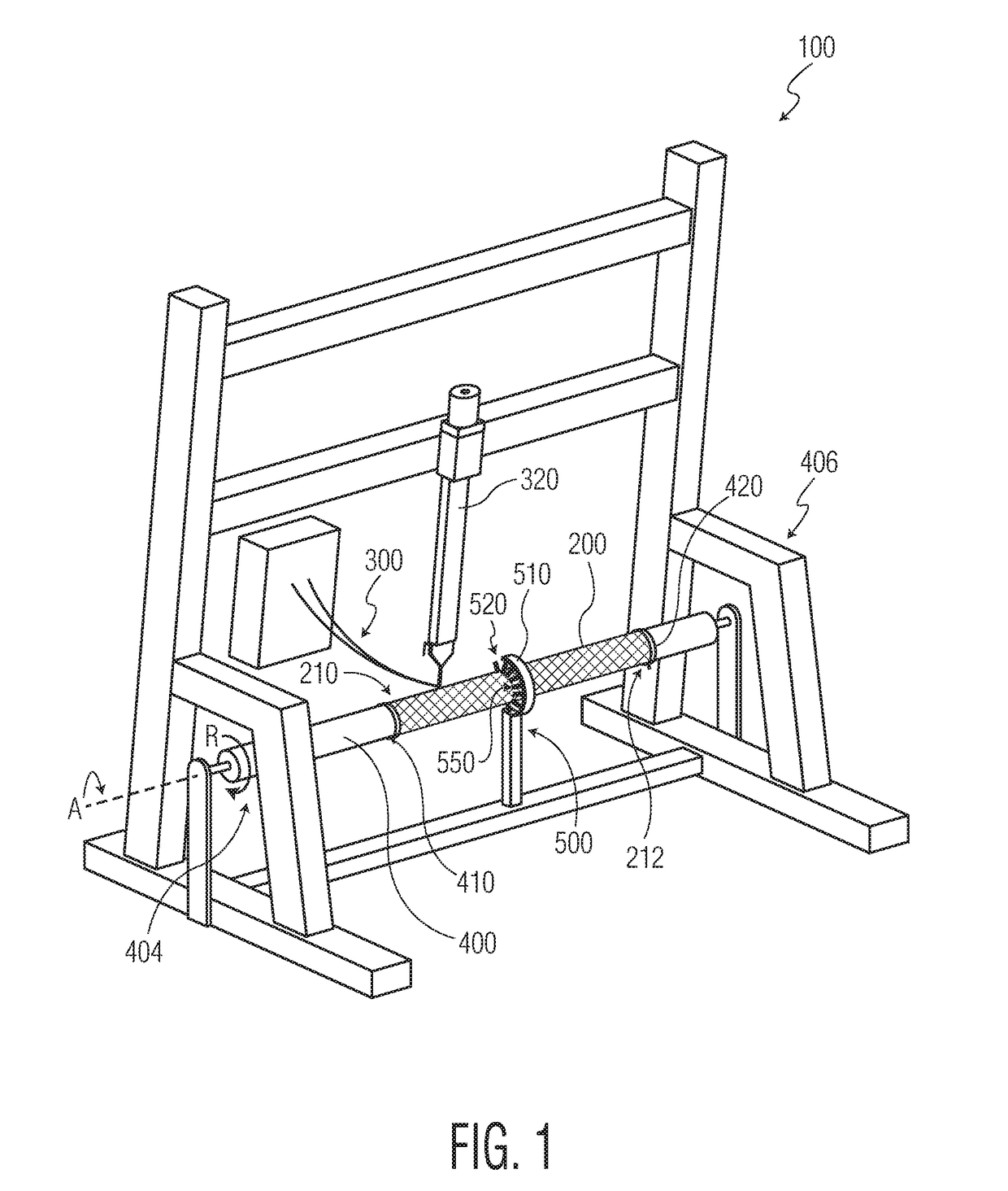
Filament winding apparatus

a technology of winding apparatus and filament, which is applied in the direction of filament handling, thin material processing, transportation and packaging, etc., can solve the problems of irrevocable damage to the article and unwound engagement, and achieve the effect of reducing or preventing the deflection of the mandrel, improving the manufacturing process, and ensuring the stability of the mandrel

Active Publication Date: 2017-06-29
KIMBERLY-CLARK WORLDWIDE INC
View PDF0 Cites 5 Cited by
  • Summary
  • Abstract
  • Description
  • Claims
  • Application Information

AI Technical Summary

Benefits of technology

The present invention aims to improve the production of elongated, hollow articles made of fiber-reinforced composite materials. The invention addresses the issue of mandrel deflection during the winding process, which can affect the quality of the finished product. By supporting the mandrel along at least one point between its first and second ends, the manufacturing process is made more efficient and the quality of the finished product is improved.

Problems solved by technology

In some cases, especially where the article and the tool bar are slightly curved in one or two directions and have a lengthwise tapered configuration, the shrinkage of the tool bar may cause undesired engagement between the tool bar and the cured article at certain locations along the tool bar due to uncontrolled mutual longitudinal movements of the tool bar and the article during the cooling phase.
This may irrevocably damage the article at certain locations when dismantling the same from the tool bar.

Method used


Image

  • Filament winding apparatus
  • Filament winding apparatus
  • Filament winding apparatus

Examples


first embodiment

[0031]In a first embodiment the present invention provides a mandrel assembly having an axis of rotation, for manufacturing filament wound parts, the mandrel assembly comprising a body having a top surface, a first end and a second end, a first pin ring disposed proximal to the first end and a second pin ring disposed proximal to the second end, and a row of support pins disposed between the first and second pin rings.

[0032]In a second embodiment the present invention provides the invention of the first embodiment wherein the support pins are retractable into the mandrel.

[0033]In a third embodiment the present invention provides the invention of any one of the first or second embodiments wherein the support pins are removable from the mandrel.

[0034]In a fourth embodiment the present invention provides the invention of any one of the first through the third embodiments wherein the support pins extend radially from the mandrel.

[0035]In a fifth embodiment the present invention provides...

eighth embodiment

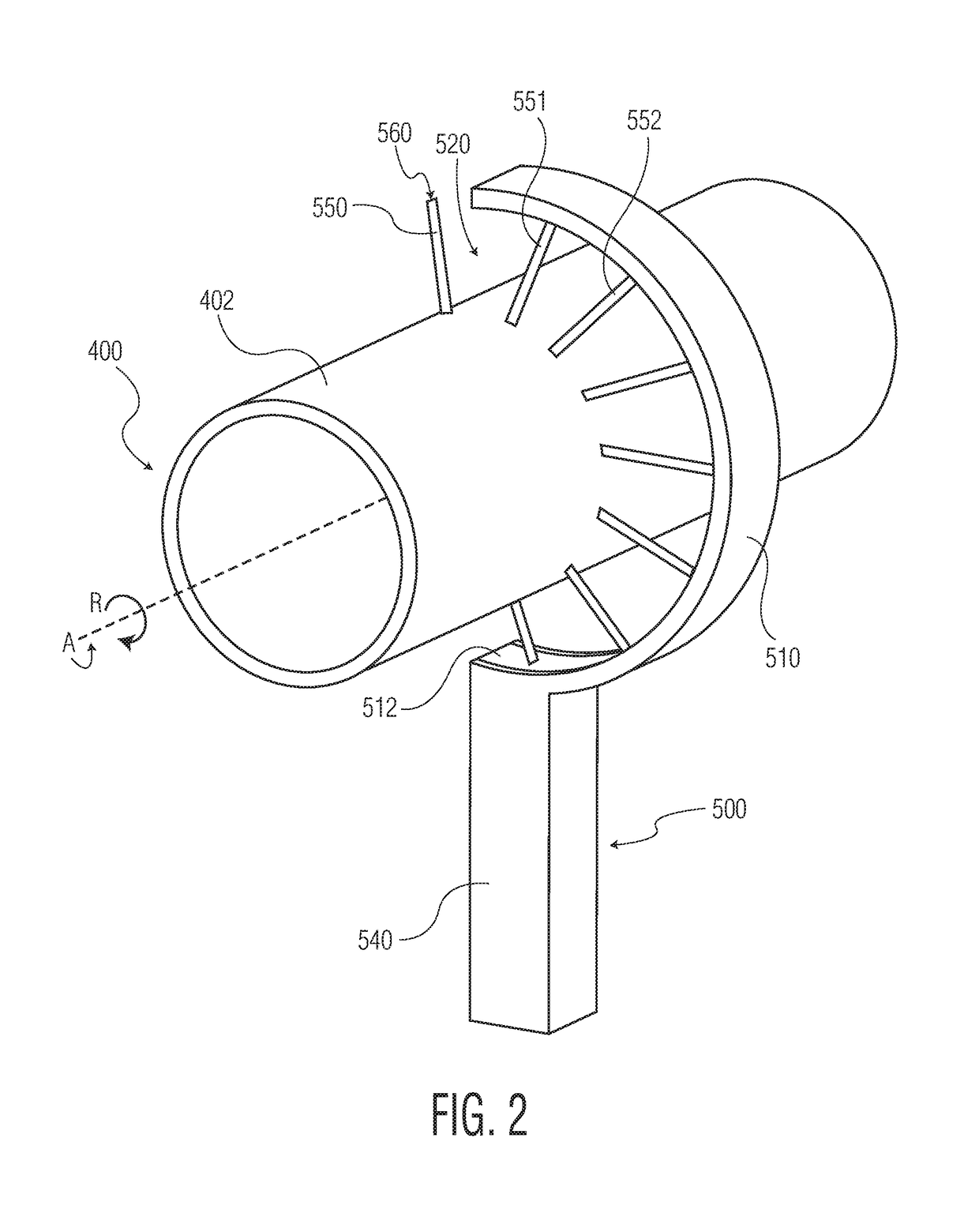
[0038]In an eighth embodiment the present invention provides a mandrel support apparatus comprising a cylindrical mandrel having an outer surface, a plurality of support pins extending radially from the top surface of the mandrel and a support assembly having a semicircular inner surface and an opening, wherein at least two support pins contact the support assembly inner surface to rotatably support the mandrel.

[0039]In a ninth embodiment the present invention provides the invention of the eighth embodiment wherein the support pins are retractable into the mandrel.

[0040]In a tenth embodiment the present invention provides the invention of any one of the eighth or ninth embodiments wherein the support pins are removable from the mandrel.

[0041]In a eleventh embodiment the present invention provides the invention of any one of the eighth through the tenth embodiments wherein the support pins extend radially from the mandrel.

[0042]In a twelfth embodiment the present invention provides t...


PUM

PropertyMeasurementUnit
circumferenceaaaaaaaaaa
temperatureaaaaaaaaaa
lengthaaaaaaaaaa

Abstract

The present invention generally relates to an improved winding apparatus useful in the production of filament wound products and particularly wound tubular products having high length to diameter ratios. The improved winding apparatus comprises a support means for supporting a rotatable mandrel during the manufacture of wound products, the support means comprising a plurality of axially spaced pins extending circumferentially around the mandrel, and a support assembly having a semicircular inner face and an opening, wherein a portion of the plurality of pins is brought into contact with the inner face of the support assembly when the mandrel is rotated.

Description

BACKGROUND OF THE DISCLOSURE[0001]When forming elongated, hollow articles of fiber-reinforced composite material, such as hollow beams or the like, a metallic core or bar is often used as a mandrel or tool, around which a plurality of layers of a resin-impregnated filament is applied by winding it in an overlapping manner to form a laminated, semi-finished article. After curing of this composite article in a subsequent heat-treatment step, e.g. in an oven or autoclave, the cured article is cooled together with the tool bar. In the cooling phase, normally in room temperature, the tool bar shrinks to a certain degree, i.e. the cross-sectional area and the length of the tool bar is somewhat reduced, whereas the dimensions of the cured article remain substantially unchanged. In some cases, especially where the article and the tool bar are slightly curved in one or two directions and have a lengthwise tapered configuration, the shrinkage of the tool bar may cause undesired engagement bet...

Claims


Application Information

Patent Timeline
Patent Type & Authority Applications(United States)
IPC IPC(8): B29C70/54B65H54/28B29C70/32B65H54/02
CPCB29C70/54B65H54/02B29K2307/04B29C70/32B65H54/28B65H54/54B65H54/72B65H75/10B29C53/66B65H81/00B65H2701/314B29C53/583
Inventor KRAUTKRAMER, ROBERT EUGENEWILSON, MATTHEW ROBERTKRAUTKRAMER, KYLE ANDREW
Owner KIMBERLY-CLARK WORLDWIDE INC
Learn More