Injection control apparatus

a control apparatus and injection tube technology, applied in the direction of auxillary shaping apparatus, ceramic shaping apparatus, manufacturing tools, etc., can solve the problems of inability to smoothly fill the gate of resin, uneven thickness, warpage, etc., to prevent the generation of sink marks or similar defects in molded products, the pressure of the cavity after the molding material has entered the cavity becomes stable and uniform, and the effect of preventing the generation of sink marks

Inactive Publication Date: 2008-09-18
SUMITOMO HEAVY IND LTD +1
View PDF3 Cites 4 Cited by
  • Summary
  • Abstract
  • Description
  • Claims
  • Application Information

AI Technical Summary

Benefits of technology

[0019]An object of the present invention is to solve the above-mentioned problems in the conventional charging methods, and to provide an injection control apparatus which prevents generation of defects in molded products and generation of gas in a cavity.
[0021]In the present invention, the drive section for injection is driven on the basis of the injection speed and the injection pressure, whereby pressure control is performed before start of charging of a molding material into a cavity, and speed control is performed after the start of charging of the molding material into the cavity. Therefore, the pressure of the cavity after the molding material has entered the cavity becomes stable and uniform.
[0022]As a result, molded products are free from defects such as uneven thickness, distortion, warpage, etc., and gas is not generated in the cavity.
[0023]Further, since a sufficient amount of a molding material can be charged into the cavity, generation of a sink mark or a like defect in molded products can be prevented.

Problems solved by technology

As a result, a molded product may involve a defect such as uneven thickness, distortion, warpage, etc., or gas may be generated in the cavity C.
However, in this case, the injection speed gradually decreases in the period between timings t2 and t3, so that resin cannot be caused to smoothly fill the gate 112 as shown in FIG. 4, and a sufficient amount of resin cannot be charged into the cavity C as shown in FIG. 5.
As a result, molded products involve defects such as formation of a sink mark.

Method used


Image

  • Injection control apparatus
  • Injection control apparatus
  • Injection control apparatus

Examples


Embodiment Construction

[0052]An embodiment of the present invention will next be described in detail with reference to the drawings. Notably, in the following description, there will be described an injection molding machine, which is one type of a molding machine.

[0053]FIG. 7 is a view showing a main portion of an injection molding machine according to the embodiment of the present invention; FIG. 8 is a first view relating to the embodiment of the present invention and showing a state within a mold apparatus; and FIG. 9 is a second view relating to the embodiment of the present invention and showing the state within the mold apparatus.

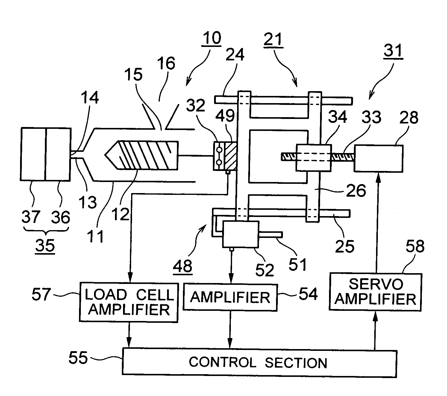
[0054]In the drawings, reference numeral 10 denotes an injection apparatus; 11 denotes a heating cylinder (a cylinder member); 12 denotes a screw (an injection member) disposed in the heating cylinder 11 such that the screw can rotate, advance, and retreat; 13 denotes an injection nozzle attached to the front end of the heating cylinder 11; 14 denotes a nozzle opening form...


PUM

PropertyMeasurementUnit
speedaaaaaaaaaa
pressureaaaaaaaaaa
pressure distributionaaaaaaaaaa

Abstract

An injection control apparatus includes an injection member; a drive section for injection; an injection-speed detection processing section which detects injection speed; an injection-pressure detection processing section which detects injection pressure; and a drive control processing section which drives the drive section for injection on the basis of the injection speed and the injection pressure to thereby perform pressure control before start of charging of a molding material into a cavity, and speed control after the start of charging of the molding material into the cavity. Since the drive section is driven on the basis of the injection speed and the injection pressure such that pressure control is performed before start of charging of a molding material into a cavity, and speed control is performed thereafter, the pressure of the cavity after the molding material has entered the cavity becomes stable and uniform.

Description

BACKGROUND OF THE INVENTION[0001]1. Field of the Invention[0002]The present invention relates to an injection control apparatus.[0003]2. Description of the Related Art[0004]Conventionally, a molding machine; for example, an injection molding machine, includes a mold apparatus, a mold-clamping apparatus, and an injection apparatus. The mold apparatus includes a stationary mold and a movable mold. The mold-clamping apparatus advances and retreats the movable mold to thereby perform mold closing, mold clamping, or mold opening of the mold apparatus. As a result of mold clamping, a cavity is formed between the stationary mold and the movable mold. Meanwhile, the injection apparatus includes a heating cylinder, and a screw which is disposed in the heating cylinder such that the screw can rotate, advance, and retreat. The injection apparatus includes a metering motor, an injection motor, etc. so as to rotate and advance the screw. When the screw is rotated in a metering step, resin is acc...

Claims


Application Information

Patent Timeline
Patent Type & Authority Applications(United States)
IPC IPC(8): B29C45/77
CPCB29C45/77B29C2945/76006B29C2945/7611B29C2945/76187B29C2945/76735B29C2945/76367B29C2945/76381B29C2945/76401B29C2945/76498B29C2945/76214
Inventor AMANO, MITSUAKISHIBATA, TATSUYAKOUMARU, IKUO
Owner SUMITOMO HEAVY IND LTD
Why Eureka
Try Eureka