
X-ray CT imaging displaying method, X-ray CT image displaying apparatus, and X-ray CT apparatus

a technology of x-ray ct and image displaying, which is applied in the field of x-ray ct image displaying method, x-ray ct image displaying apparatus, and x-ray ct apparatus, which can solve the problem of difficult patient understanding the condition of the portion

Inactive Publication Date: 2008-09-18
MORITA MFG CO LTD
View PDF0 Cites 16 Cited by
  • Summary
  • Abstract
  • Description
  • Claims
  • Application Information

AI Technical Summary

Benefits of technology

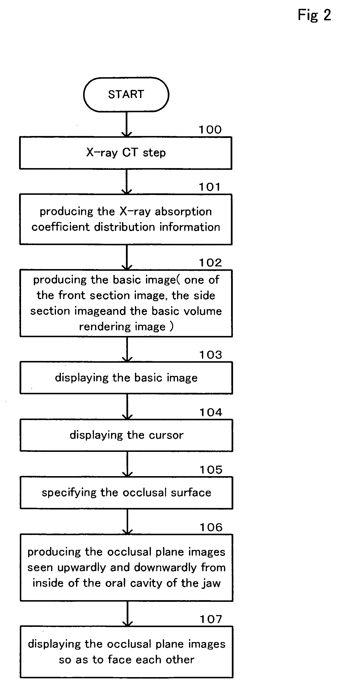
[0037]According to the claim 3, the occlusal surface specifying step comprises a step of producing and displaying at least one of the front sectional image, the side sectional image, and the basic volume rendering image as a basic image from the X-ray absorption coefficient distribution information obtained from the X-ray CT of the head, and a step of receiving an operation of a cursor to specify the occlusal surface on at least one of the front sectional image, the side sectional image, and the basic volume rendering image. Therefore, the operator can specify the occlusal surface by the operation of a cursor on at least one of the front sectional image, the side sectional image, and the basic volume rendering image. It is useful for the operator and the patient to be able to display the preferable occlusal plane surface image precisely with a simple operation like a cursor operation.

Problems solved by technology

However, with these displaying methods, the operator has to understand the condition of the portion to be operated only from the layer plane image or the screen photograph, therefore it is difficult for the patient to understand the condition of the portion to be operated when the operator explains it to the patient.

Method used


Image

  • X-ray CT imaging displaying method, X-ray CT image displaying apparatus, and X-ray CT apparatus
  • X-ray CT imaging displaying method, X-ray CT image displaying apparatus, and X-ray CT apparatus
  • X-ray CT imaging displaying method, X-ray CT image displaying apparatus, and X-ray CT apparatus

Examples


Embodiment Construction

[0060]The embodiments of the present invention are explained as follows.

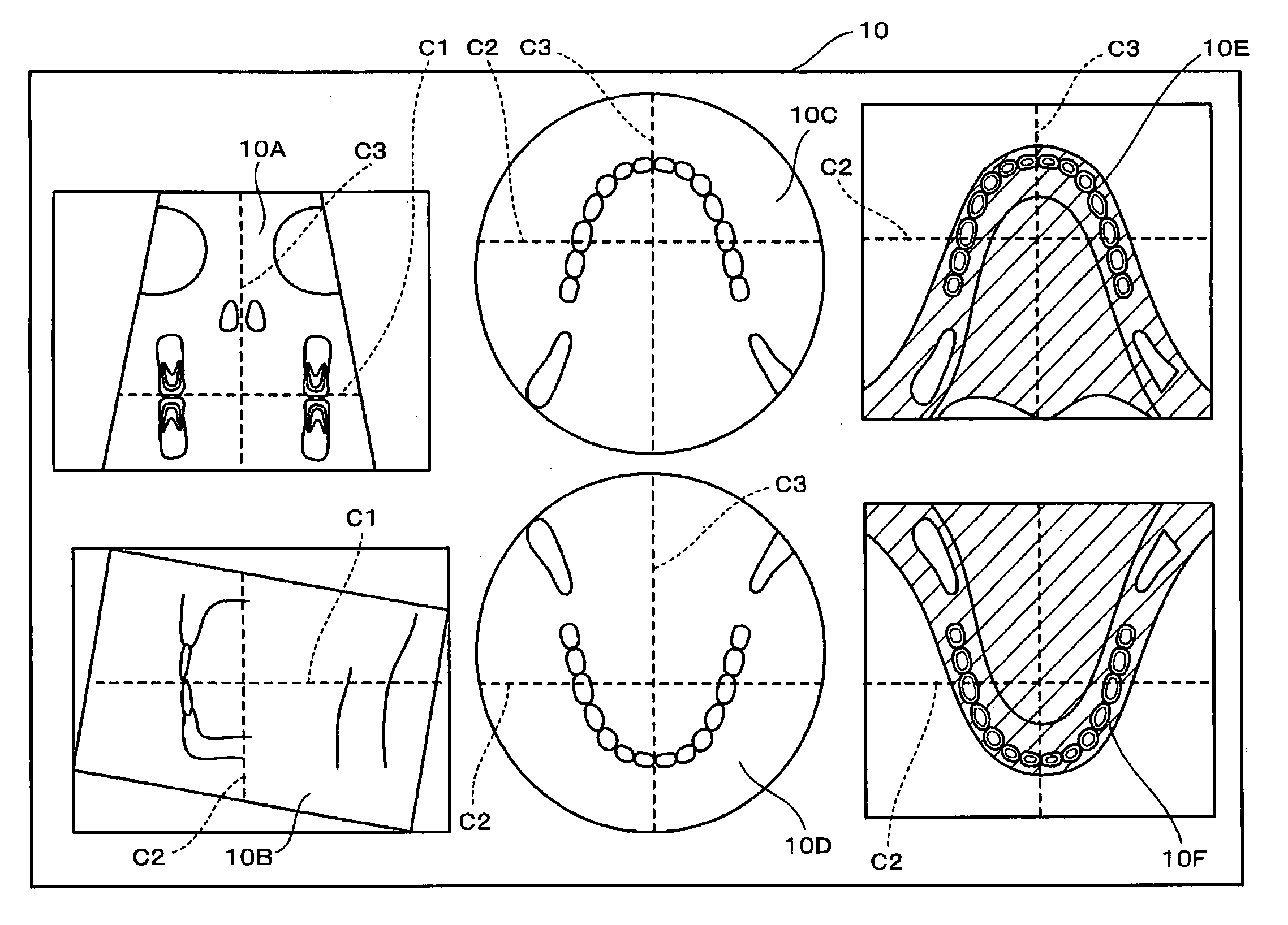
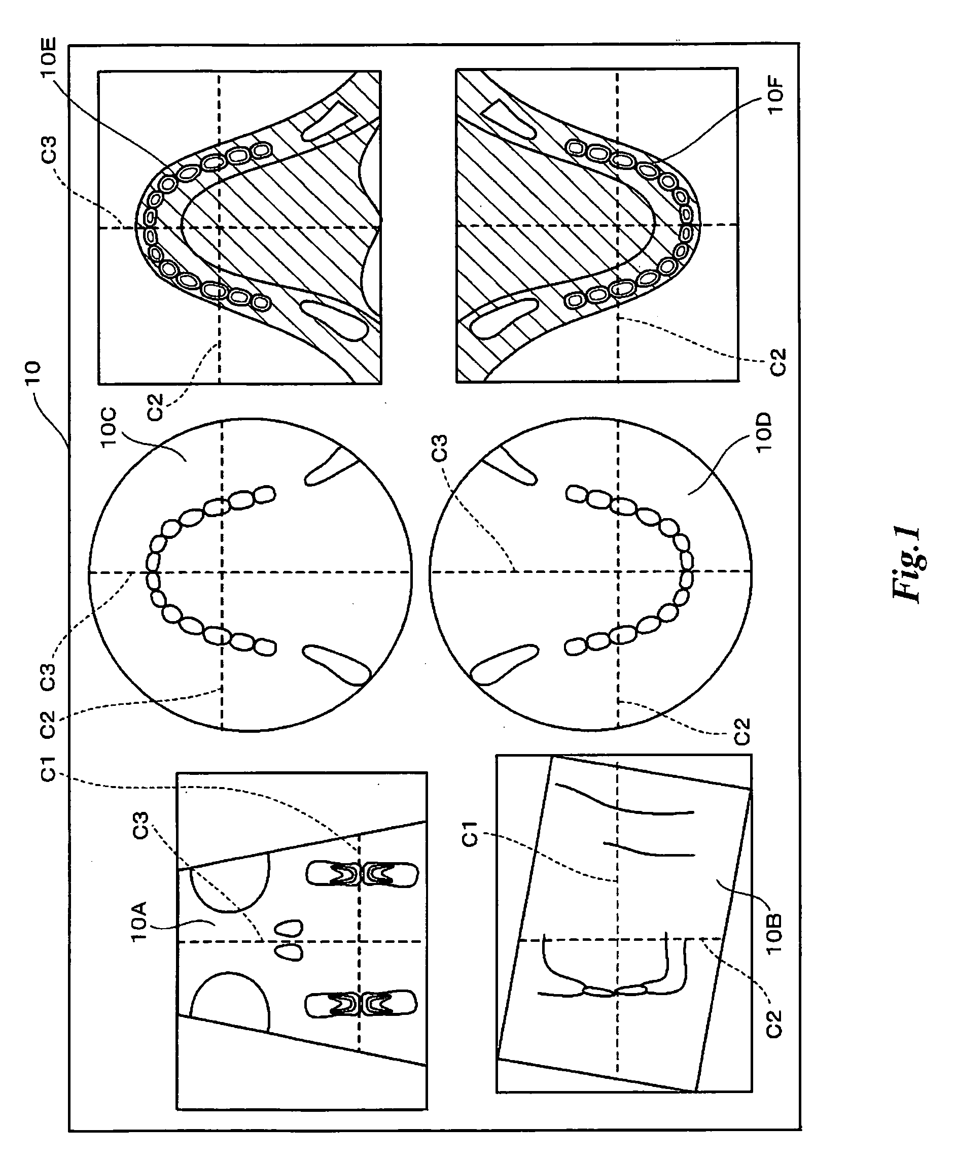
[0061]FIG. 1 shows an example of the displaying embodiment of the basic image and the occlusal plane surface images upwardly and downwardly seen from the inside of the oral cavity of the jaw in the displaying portion. The displaying portion 10 mentioned here can carry out the displaying method of the present invention, if the displaying portion 10 is provided with a general-purpose displaying apparatus such as a liquid crystal display.

[0062]FIG. 2 shows the flow chart (100-107) explaining an example of the displaying method of the X-ray CT image of the present invention.

[0063]FIG. 3 shows a drawing explaining the basic principle to produce the basic image from the X-ray image data of the object. FIG. 4 shows a drawing explaining the basic principle to produce the volume rendering image upwardly and downwardly seen from the inside of the oral cavity of the jaw from the X-ray image data of the head.

[0064]The X-ray...


PUM


Abstract

An X-ray CT image displaying method, an X-ray CT image displaying apparatus, and an X-ray CT apparatus are proposed and disclosed, in order to produce and display the occlusal plane surface image seen upwardly and downwardly from the inside of the oral cavity of the jaw so as to face each other on the basis of the occlusal surface, if the occlusal surface which is important for the dental diagnosis is specified on the basic image or the image data according to the X-ray absorption coefficient distribution information produced from X-ray projection image of the head of an object to be examined.The X-ray CT image displaying method for displaying X-ray CT image of the head by X ray CT comprises: an occlusal surface specifying step of receiving an occlusal surface specifying in the X-ray image data obtained by X-ray CT of the head; an image producing step of producing from the X-ray image data an upward occlusal plane images seen upwardly from inside of the oral cavity of the jaw of the head and a downward occlusal plane image seen downwardly from the inside of the oral cavity both on the basis of the occlusal surface specified by the occlusal surface specifying step; and a displaying step of displaying the two upward and downward occlusal plane images produced by the image producing step in a manner that the upward and downward occlusal plane images face each other.

Description

TECHNICAL FIELD[0001]The present invention relates to the improvement of an X-ray CT image displaying method, an X-ray CT image displaying apparatus, and an X-ray CT apparatus.[0002]According to the method for example disclosed in JP-A-H08-215192 as a processing method of an X-ray CT image, the oblique sectional images which include the oblique line and is perpendicular to the panoramic curve is displayed by picturing the arbitrary oblique line in the layer image.BACKGROUND ART[0003]According to the method disclosed in JP-A-H08-215192, if the layer image of the teeth of the object is produced and displayed from the continuous slice image obtained by an X-ray picturing apparatus and a plural of coordinated points to specify the panoramic curve is inputted on the layer image by operator, then the panoramic curve which connects the points are pictured on the layer image and the panoramic layer image which includes the pictured panoramic curve and is perpendicular to the layer image is ...

Claims


Application Information

Patent Timeline
IPC IPC(8): G06K9/00A61B6/03
CPCA61B6/032A61B6/14A61B6/5223A61B6/501A61B6/463A61B6/51
Inventor SADAKANE, TOMOYUKI
Owner MORITA MFG CO LTD
Learn More