Braking Device For an Electric Motor

a technology of braking device and electric motor, which is applied in the direction of generator/motor, dynamo-electric machine, electrical apparatus, etc., can solve the problems of friction on the rail and unfavorable electric motor dynamic behavior

Inactive Publication Date: 2008-09-18
ETEL SA
View PDF3 Cites 6 Cited by
  • Summary
  • Abstract
  • Description
  • Claims
  • Application Information

AI Technical Summary

Benefits of technology

[0005]Example embodiments of the present invention avoid the above-mentioned disadvantages by providing a braking device of the type having brake pads, which cooperate with a brake rail or brake disk, and which braking device makes it possible to maintain precisely the position of the movable part along the three main axes when operating this braking device.
[0007]Since the brake pads connected to the distancing device are mounted on the support of the braking device with the aid of an elastically deformable fastening device, the deformations experienced by the assembly including the brake pads are no longer transmitted to the support such that the movable element remains in a stable position when the braking device is operated. In addition, the elastically deformable fastening device allows for the parasitic braking due to the friction of the brake disks on the brake rail to be greatly reduced when the latter and / or the guide device is / are not entirely straight. The two brake pads and their connecting element may experience a lateral displacement under the influence of a relatively small force such that the pressure that is exerted on the one or the other of the disks connected to the brake pads when the brake is released remains relatively low.
[0008]In the example embodiment described below, the distancing device of the brake pads is formed by a piezoelectric element that is situated between these two brake pads. In the example embodiment, the elastically deformable fastening device includes at least two plates that have a certain elasticity along a direction at right angles with respect to the brake rail, but that have a good stiffness along the direction parallel to this brake rail. This latter feature guarantees a precise and stable positioning along the displacement direction of the movable part of the electric motor and a stable maintenance of the given position of this movable part when stopping when operating the braking device for activating the brake. The elastic plates are dimensioned such that they absorb the mechanical stresses and deformations of the two brake pads and of the material elements connecting the latter.

Problems solved by technology

Most conventional braking devices of the type having brake pads have a main problem of changing the position of the movable part when operating the braking device.
Another problem encountered in braking devices of this kind results from the fact that the brake rail or the guide system of the movable part (which may be formed by the brake rail) is not always entirely straight.
In such a case, it is possible that the brake disks, which are mounted on the brake pads, cause friction on the rail.
The rigid construction of the conventional braking devices produces a significant braking effect at such frictions, which is unfavorable for the dynamic behavior of the electric motor.

Method used


Image

  • Braking Device For an Electric Motor
  • Braking Device For an Electric Motor
  • Braking Device For an Electric Motor

Examples


Embodiment Construction

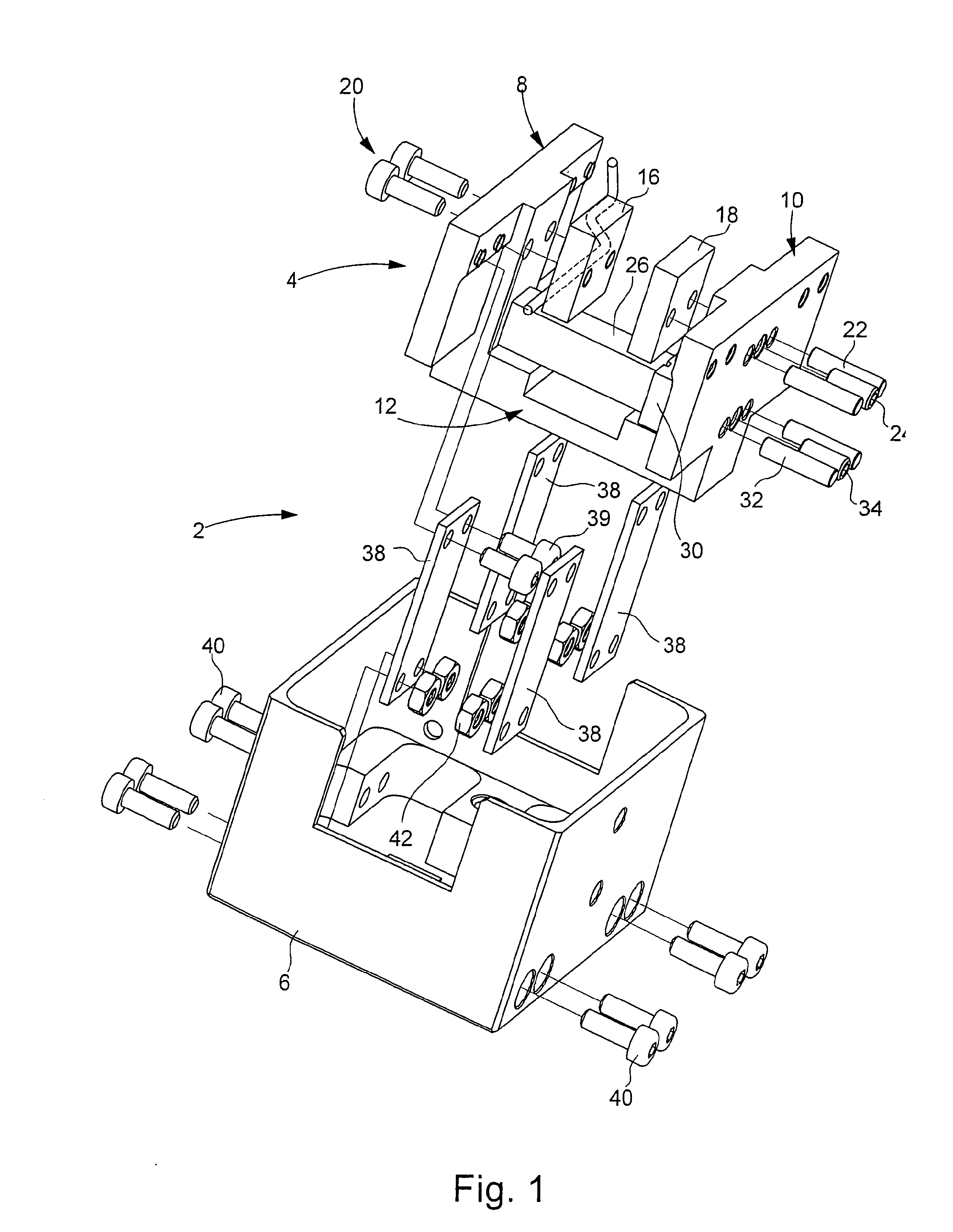
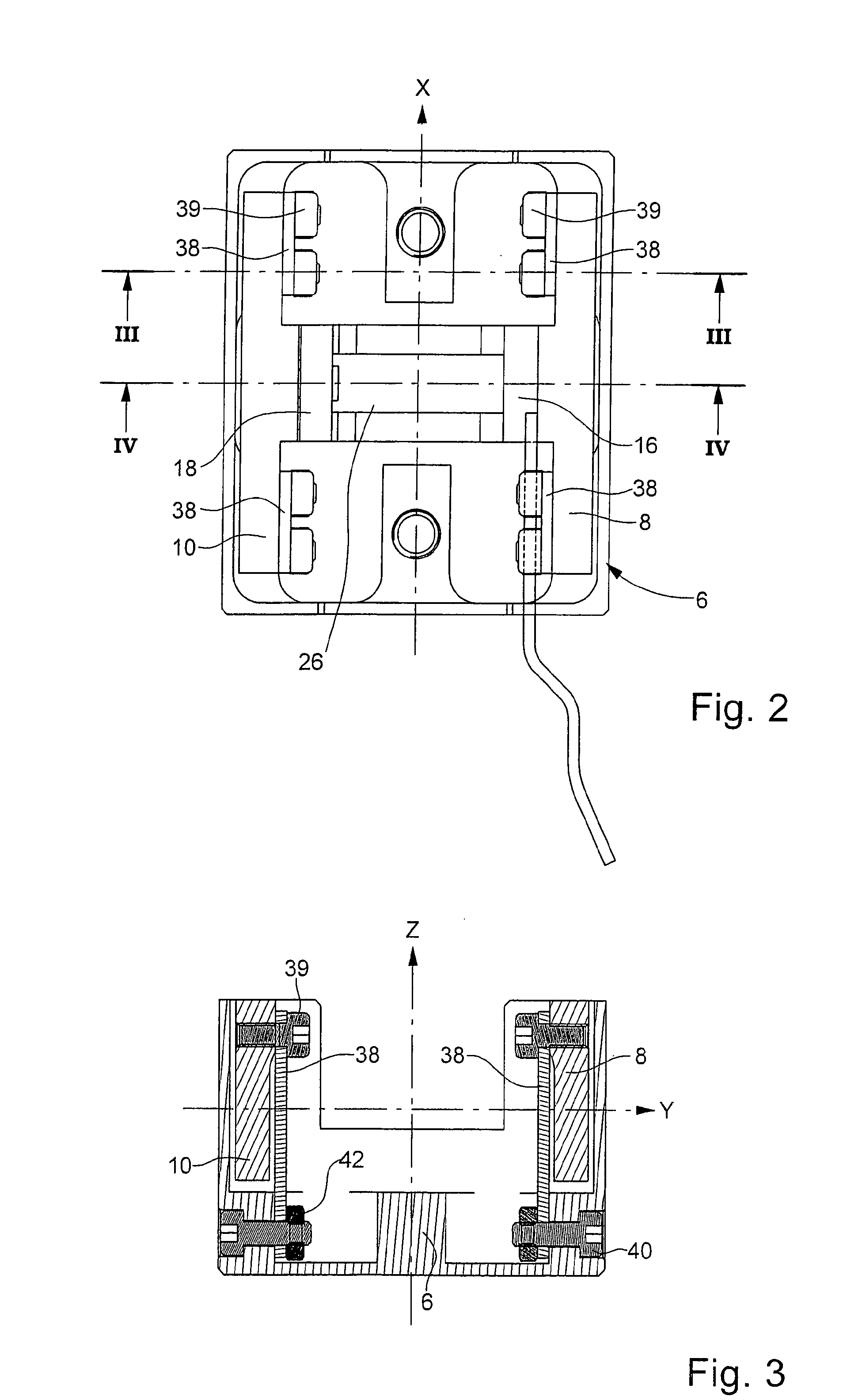
[0017]A braking device according to an example embodiment of the present invention is described below with reference to the Figures.

[0018]Braking device 2 includes a first assembly 4 and a support 6 that forms a housing. Assembly 4 includes two brake pads 8 and 10, which are connected by connecting element 12 that extends at right angles with respect to the two brake pads and to guide rail 14, which is shown schematically in FIG. 4. Guide rail 14 defines a brake rail. A brake disk suitable for the braking function may be provided however. In the example embodiment shown, connecting element 12 forms one and the same piece together with the two brake pads. In other example embodiments, however, the brake pads may be connected to each other by different elements that are fastened to the brake pads. Each brake pad is connected to a brake disk 16 or 18. Disk 16 is provided to be fixed and is mounted on brake pad 8 with the aid of two screws 20. Disk 18 is mounted on brake pad 10 with the...


PUM


Abstract

A braking device for an electric motor includes two brake pads, which are connected to brake disks, which cooperate with a brake rail. The two brake pads are rigidly connected by a connecting element, which is able to experience a certain deflection under the influence of a piezoelectric element, which is used to distance the two brake pads from each other. An assembly, which includes the two brake pads and their connecting element, is fastened on a support by a fastening device, which is elastically deformable along the direction at right angles with respect to the brake rail and to the two brake pads. The elastically deformable fastening device is formed of plates, which are connected on one end to the assembly and on the other end to the support.

Description

FIELD OF THE INVENTION[0001]The present invention relates to a braking device for an electric motor, e.g., a linear motor, of the type having two brake pads that cooperate with a brake rail that is inserted between these two brake pads. Braking is achieved by brake disks, which are connected with the two brake pads, laterally pressing against a brake rail or brake disk. In order to operate the braking device, i.e., in order to activate or release the brake, the braking device includes a distancing device connected to the two brake pads and that make it possible to change the clearance between these two brake pads in order activate or deactivate the braking device.BACKGROUND INFORMATION[0002]Certain braking devices having two brake pads, which cooperate with a brake rail or in a similar manner with a brake plate or brake disk, are conventional. For numerous applications, it is necessary to maintain a precise position of the movable part of an electric motor when stopping; that is, no...

Claims


Application Information

Patent Timeline
Patent Type & Authority Applications(United States)
IPC IPC(8): H02K7/102F16D63/00H02K41/02F16D65/22
CPCF16D2121/30F16D63/008F16D65/22F16D65/092
Inventor MOREL, JEAN-PIERRE
Owner ETEL SA
Why Eureka
Try Eureka