
Adjustable clip advance

a conveyor and clip technology, applied in the field of adjustable clip advance, can solve the problems of impeded or prevented engagement, time-consuming and thus cost-intensive clip conveyor apparatuses known in practice, and suffer from further disadvantages, and achieve the effect of simple adjustment and simple structur

Active Publication Date: 2008-09-18
POLY CLIP SYST
View PDF14 Cites 1 Cited by
  • Summary
  • Abstract
  • Description
  • Claims
  • Application Information

AI Technical Summary

Benefits of technology

The present invention provides a clip conveyor apparatus for a clipping machine that is simple and allows for easy adjustment of the clip line's advance length or stroke without the need for tools or disassembly of the clipping machine. The apparatus includes an advance element that is coupled to a drive unit and can be adjusted in position without a tool. The position of the advance element can be adjusted by an eccentric, which allows for a simple and reliable adjustment of the advance stroke to the size of the clips. The apparatus also includes a retaining device that prevents the clip line from slipping back after the clip has been severed from the line. The retaining device can be adjusted to different clip sizes. Overall, the invention provides a convenient and efficient solution for adjusting the clip conveyor apparatus in a clipping machine.

Problems solved by technology

This is also time-consuming and thus cost-intensive.
The clip conveyor apparatuses known in practice suffer from a further disadvantage.
If the clip line is subjected to a tensile stress due to the advance movement, it can be pulled back upon separation of the foremost clip from the clip line in the engagement region of the advance element, in opposite relationship to the advance direction, and that impedes or prevents a desired engagement.

Method used


Image

  • Adjustable clip advance
  • Adjustable clip advance
  • Adjustable clip advance

Examples


Embodiment Construction

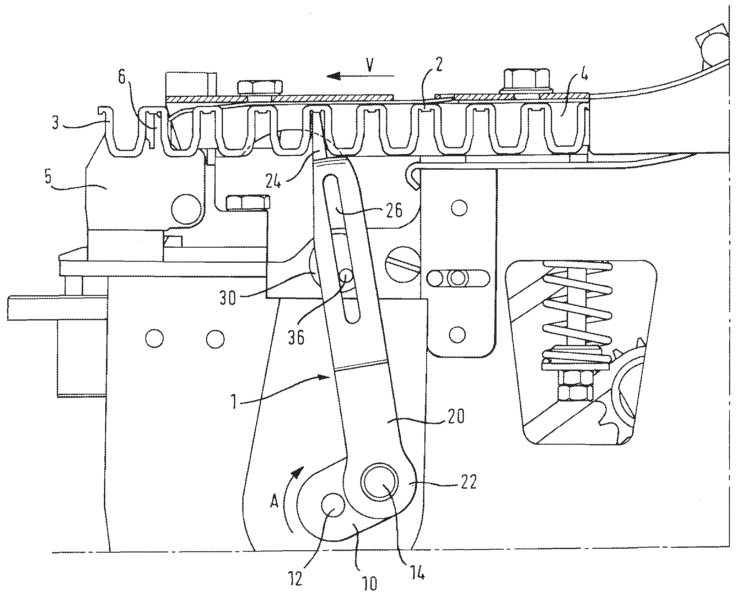
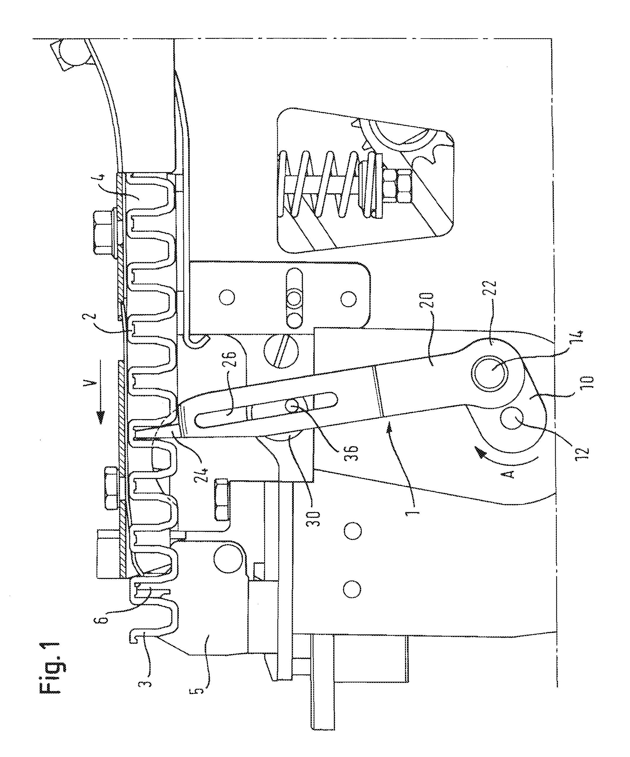
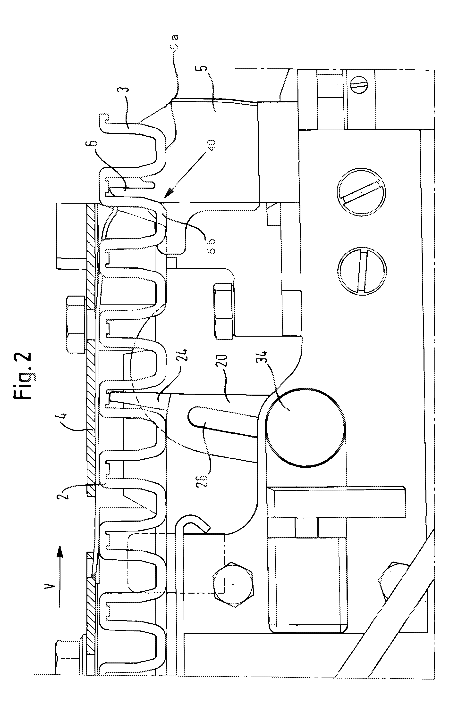
[0031]The embodiment described hereinafter of a clip conveyor apparatus according to the invention is used in for example sausage clipping machines. As can be seen from FIG. 1 the clip conveyor apparatus 1 includes a drive unit 10, an advance or transport element 20, an adjusting device 30 and a retaining device 40.

[0032]The drive unit 10, which in the illustrated embodiment has an eccentric as the drive element, is disposed beneath the horizontally extending clip line 2 that is guided in a clip guide 4. The eccentric is mounted on a rotatably mounted drive shaft 12. The eccentric is arranged in rotationally and axially fixedly mounted relationship in such a way that its eccentric pin or journal describes a circle extending in the plane of FIG. 1. The eccentric can be caused to rotate for example by a belt or chain drive (not further shown), which is driven by the main machine drive or by the main machine shaft. It is equally possible for the drive of the eccentric to be driven by a...


PUM


Abstract

The invention concerns a clip conveyor apparatus for conveying a clip line (2) comprising a plurality of clips in a clipping machine, in particular a sausage clipping machine, comprising a drive unit (10) and an advance element (20) which is coupled with its drive end (22) to the drive unit (10) and is drivable by the drive unit (10) in such a way that its conveyor end (24) describes an elliptical path and for stepwise conveyance of the clip line (2) engages into intermediate spaces between two clips of the clip line (2) and conveys same stepwise in the advance direction (V), wherein there is provided an adjusting device (30) having a pivot axis (36) about which the transport element (20) is pivotable and which is adjustable in its position without a tool in such a way that at least one of the axes of the elliptical path described by the conveyor end (24) is variable.

Description

[0001]This patent application claims priority to German patent application DE 10 2007 012 778.4, filed Mar. 16, 2007, which is hereby incorporated herein by reference.BACKGROUND OF THE INVENTION[0002]The present invention concerns a clip conveyor apparatus for conveying a clip line consisting of a plurality of clips in a clipping machine, in particular a sausage clipping machine.[0003]In particular, the invention concerns a clip conveyor apparatus for conveying a closure clamp line or clip line consisting of a plurality of closure clamps or clips in a clipping machine, in particular a sausage clipping machine, where the clip conveyor apparatus has a drive unit and an advance or transport element. The advance element is coupled with its drive end to the drive unit. In that arrangement, it is drivable by the drive unit in such a way that its conveyor end that is in opposite relationship to the drive end describes an elliptical path and, for stepwise conveyance of the clip line, engage...

Claims


Application Information

Patent Timeline
Patent Type & Authority Applications(United States)
IPC IPC(8): B65G17/20
CPCA22C11/125
Inventor EBERT, DETLEFHUMMEL, MICHAEL
Owner POLY CLIP SYST
Learn More