
Tracking an object with multiple asynchronous cameras

a technology of asynchronous cameras and objects, applied in the field of tracking objects, can solve the problems of difficult detection of failures, cumbersome synchronization of cameras, and questionable quality of resulting position estimates

Active Publication Date: 2008-09-11
SPORTSMEDIA TECH CORP
View PDF93 Cites 102 Cited by
  • Summary
  • Abstract
  • Description
  • Claims
  • Application Information

AI Technical Summary

Benefits of technology

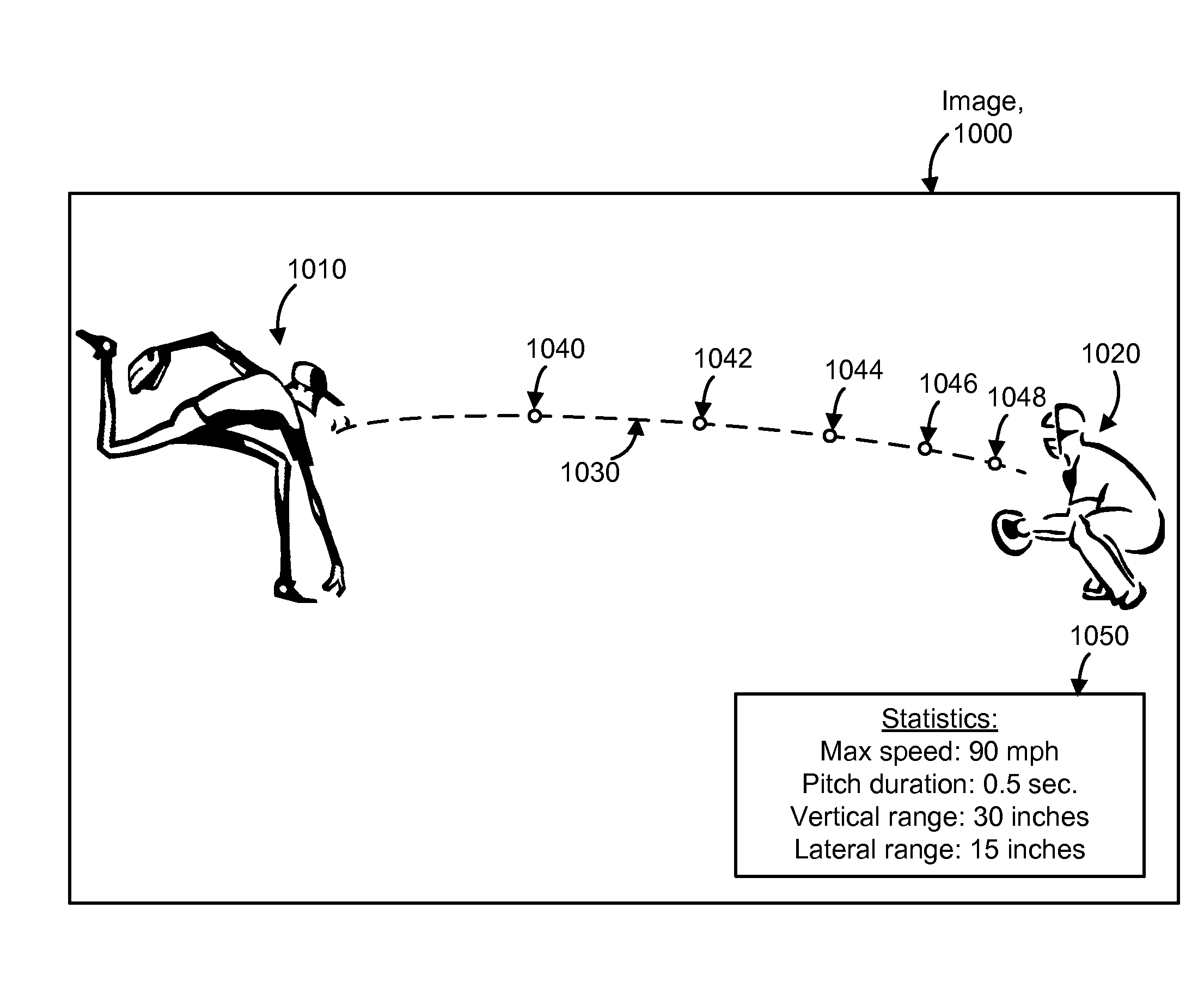
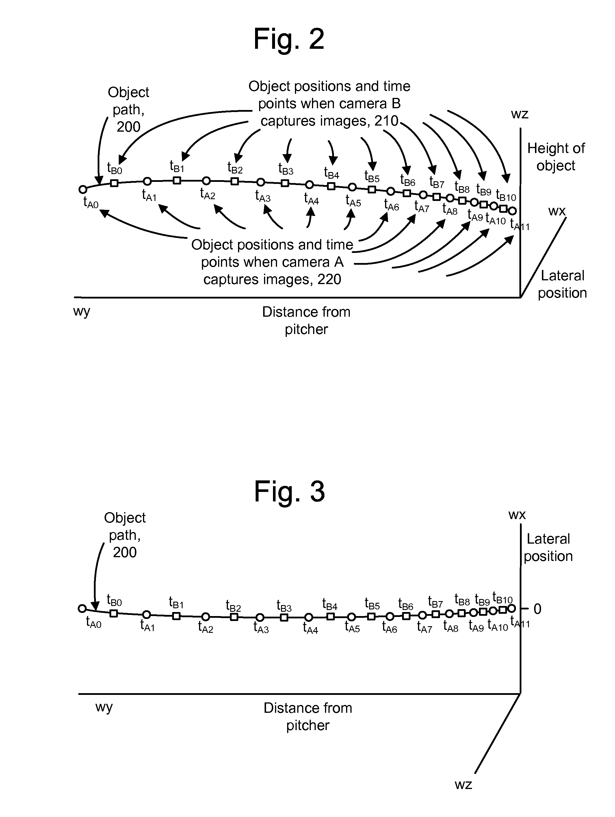
The present invention provides a system and method for determining the position and path of an object using asynchronous cameras. This can be useful in applications such as sports events or video games. The method involves receiving images of the moving object from multiple cameras at different time points during a time interval and determining the position of the object in each image. By solving for coefficients of motion, the system can determine the path of the object during the time interval. The invention can enhance video of the moving object to depict at least a portion of the path and provide statistics regarding the path. The system can also store the results for later use. Overall, the invention allows for more accurate and precise tracking of moving objects in various applications.

Problems solved by technology

However, synchronizing the cameras is cumbersome and time consuming.
In addition to the extra equipment which is needed, e.g., cables and connectors, and the labor required to provide the clock signal, which is in itself a significant part of system set up, failures can be difficult to detect.
As a result, the quality of the resulting position estimate can be questionable.
One subtle way in which the synchronization can fail is when the signal path of a clock signal to the cameras has inadequate termination.
This can cause signal reflections and signal delays, effectively destroying the synchronization.

Method used


Image

  • Tracking an object with multiple asynchronous cameras
  • Tracking an object with multiple asynchronous cameras
  • Tracking an object with multiple asynchronous cameras

Examples


Embodiment Construction

[0024]The present invention provides a system and method for determining the position and / or path of an object using asynchronous cameras. Asynchronous cameras are free running and use their internal clocks for determining an image capture rate. Thus, asynchronous cameras can capture images at different time points rather than at common time points.

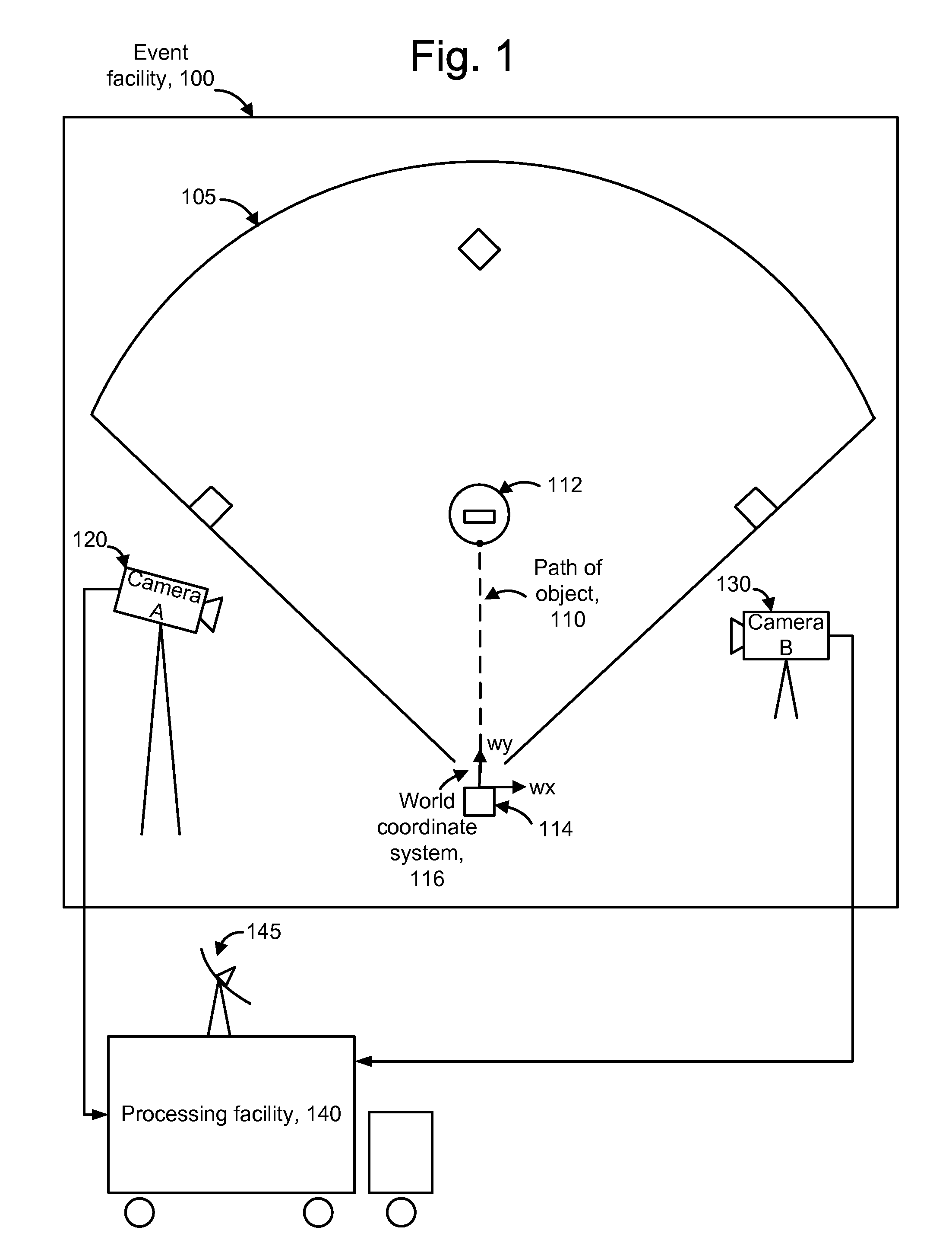
[0025]FIG. 1 depicts a system for tracking an object in an event facility. In one example application, a game object such as a baseball is tracked at an event facility 100 such as a baseball stadium. It will be appreciated that many other applications are possible. For example, a surveillance application can track cars and people, and a sports application can track the trajectory of a golf ball, football, tennis ball, hockey puck or other object. The event facility includes a baseball diamond infield 105 having a pitcher's mound 112 and a home plate 114. A path 110 depicts the trajectory of a baseball thrown from the pitcher to the catche...


PUM


Abstract

The path and / or position of an object is tracked using two or more cameras which run asynchronously so there is need to provide a common timing signal to each camera. Captured images are analyzed to detect a position of the object in the image. Equations of motion for the object are then solved based on the detected positions and a transformation which relates the detected positions to a desired coordinate system in which the path is to be described. The position of an object can also be determined from a position which meets a distance metric relative to lines of position from three or more images. The images can be enhanced to depict the path and / or position of the object as a graphical element. Further, statistics such as maximum object speed and distance traveled can be obtained. Applications include tracking the position of a game object at a sports event.

Description

CROSS-REFERENCE TO RELATED APPLICATIONS[0001]This application claims the benefit of U.S. provisional patent application No. 60 / 893,082, filed Mar. 5, 2007, and incorporated herein by reference.BACKGROUND OF THE INVENTION[0002]Many applications employ object tracking techniques. For example, cars and people may be tracked in surveillance applications, the trajectory of a golf ball may be tracked in a golf training aid application, and an object in a sporting event may be tracked to enhance a video presentation of the event. Typically, object tracking techniques use two or more cameras which are synchronized to capture images of the object at the same time. The synchronized images are used to determine or estimate the position of a moving object which is depicted in the synchronized images. However, synchronizing the cameras is cumbersome and time consuming. For example, a high resolution clock signal must be made available simultaneously at each of the cameras, e.g., using the techni...

Claims


Application Information

Patent Timeline
Patent Type & Authority Applications(United States)
IPC IPC(8): G06K9/00
CPCA63B24/0003G06T2207/30224A63B69/3658A63B71/06A63B2024/0028A63B2024/0034A63B2220/05A63B2220/20A63B2220/30A63B2220/40A63B2220/62A63B2220/806A63B2220/89A63B2225/50A63B2243/0004G06T7/20G06T7/2093A63B24/0021A63B2102/18G06T7/292A63B2243/0066A63B2102/02A63B2102/32
Inventor WHITE, MARVIN S.ALT, ALINA
Owner SPORTSMEDIA TECH CORP
Learn More