
Bit mounting devices

Inactive Publication Date: 2008-09-11
MAKITA CORP
View PDF45 Cites 38 Cited by
  • Summary
  • Abstract
  • Description
  • Claims
  • Application Information

AI Technical Summary

Benefits of technology

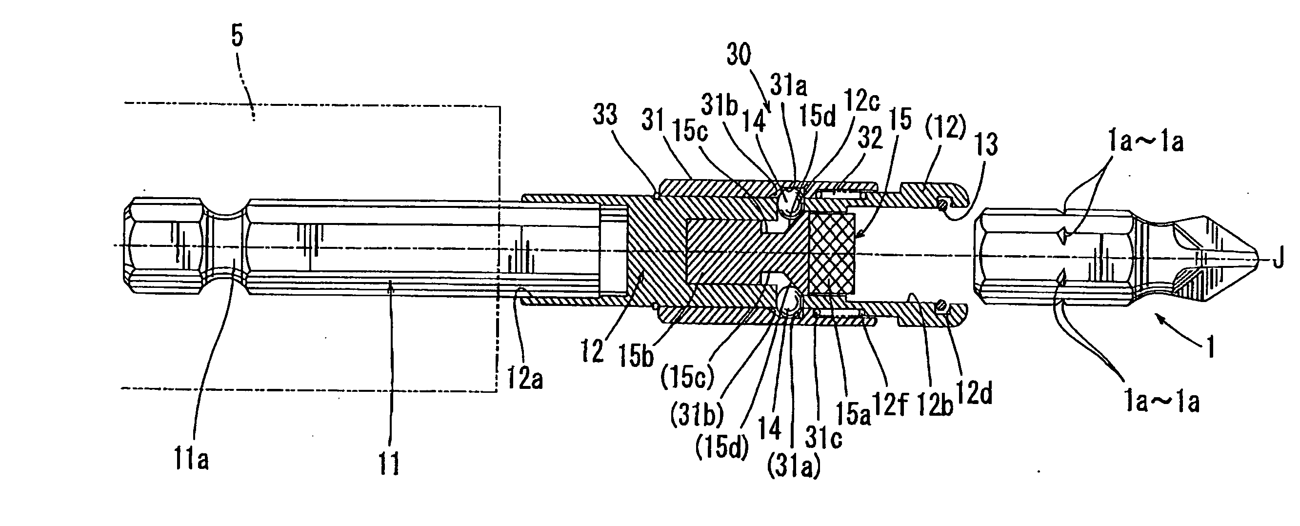
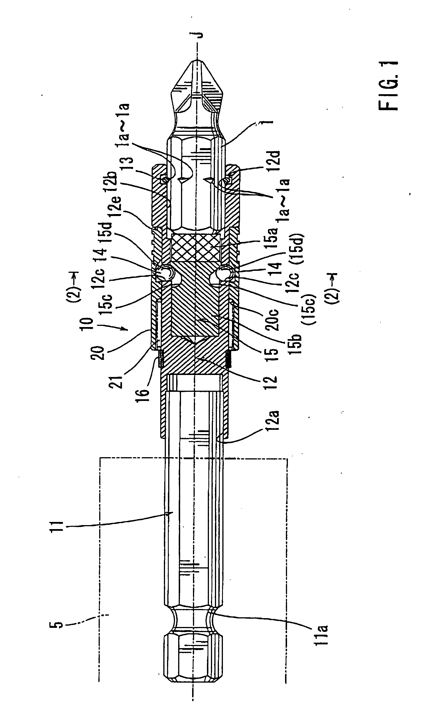
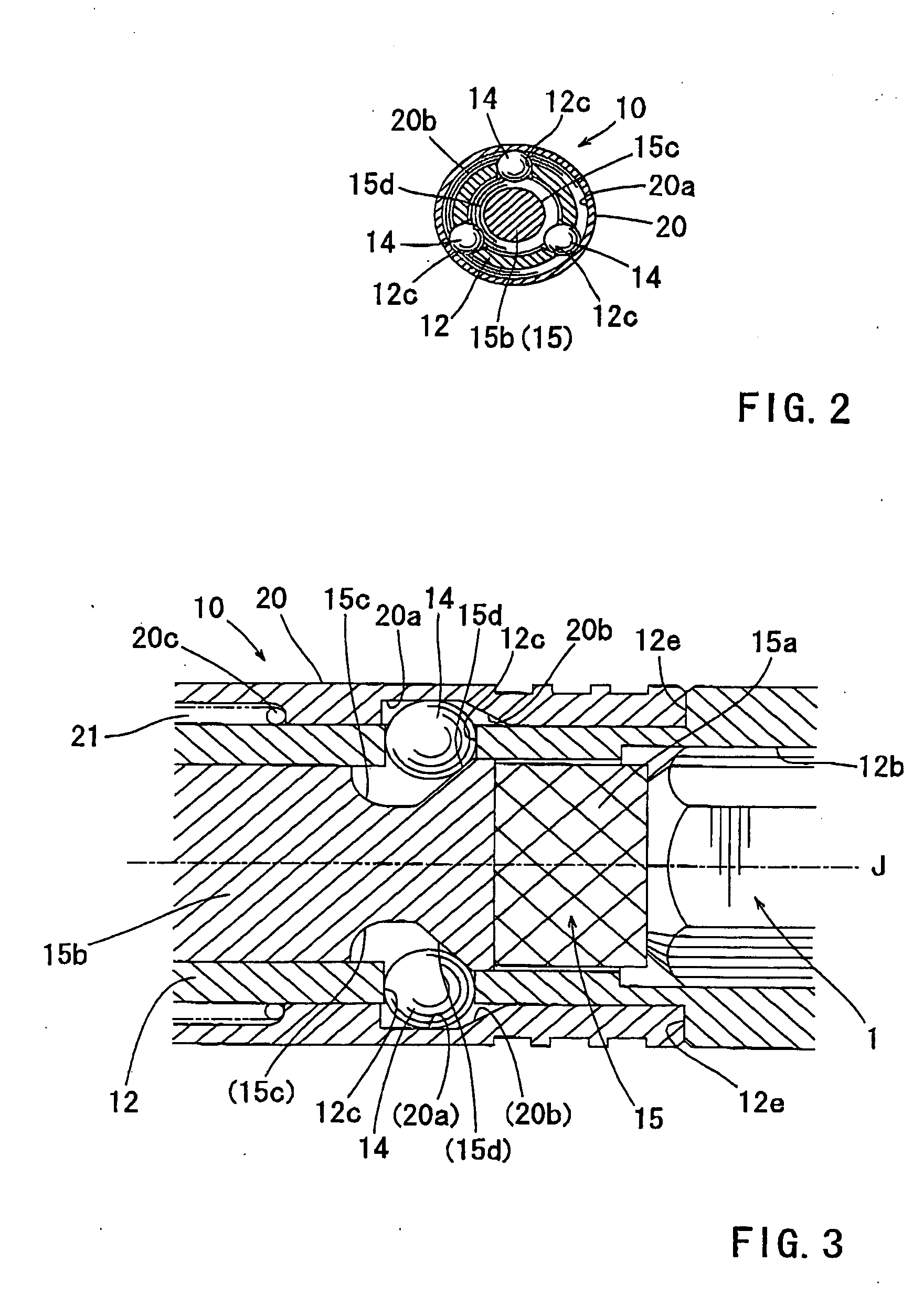
[0025]With this arrangement, the stop ring that directly engages the tool bit can restrict the movement of the tool bit in the bit removing direction. Therefore, it is possible to use popularly used magnetic connecting bits as a tool bit, so that the compatibility of the bit mounting device can be ensured.
[0012]One aspect according to the present invention includes a bit mounting device for a power tool. The bit mounting device includes a holder that may be mounted to a spindle of the power tool or may be a part of the spindle. A bit push member is disposed within a bit receiving hole that is formed in the holder for receiving a tool bit. An operation member is movably attached to the holder. The movement of the operation member is transmitted to the bit push member via a transmission mechanism, so that the tool bit is pushed in a removing direction from the bit receiving hole by the bit push member. The transmission mechanism may be a cam mechanism, a gear mechanism, or any other suitable mechanism.
[0012]One aspect according to the present invention includes a bit mounting device for a power tool. The bit mounting device includes a holder that may be mounted to a spindle of the power tool or may be a part of the spindle. A bit push member is disposed within a bit receiving hole that is formed in the holder for receiving a tool bit. An operation member is movably attached to the holder. The movement of the operation member is transmitted to the bit push member via a transmission mechanism, so that the tool bit is pushed in a removing direction from the bit receiving hole by the bit push member. The transmission mechanism may be a cam mechanism, a gear mechanism, or any other suitable mechanism.
[0024]In one embodiment, a bit mounting device for mounting a tool bit on a spindle of a rotary tool includes a mount shaft and a holder. The mount shaft is adapted to be mounted to the spindle. The holder defines a bit receiving hole that has the same axis as the mount shaft. A stop ring is attached to an inner circumference of an inlet portion of the bit receiving hole and is directly engageable with the tool bit for preventing the tool bit from being removed from the bit receiving hole. A bit push member is positioned within the bit receiving hole on the side of a bottom of the bit receiving hole and is movable in a bit mounting direction and a bit removing direction opposite to the bit mounting direction. An operation sleeve is attached to the holder and is movable in opposite directions parallel to the axis of the mount shaft. The movement of the operation sleeve in one of the opposite directions causes the bit push member to move in the bit removing direction, so that the tool bit is disengaged from the stop ring.
[0012]One aspect according to the present invention includes a bit mounting device for a power tool. The bit mounting device includes a holder that may be mounted to a spindle of the power tool or may be a part of the spindle. A bit push member is disposed within a bit receiving hole that is formed in the holder for receiving a tool bit. An operation member is movably attached to the holder. The movement of the operation member is transmitted to the bit push member via a transmission mechanism, so that the tool bit is pushed in a removing direction from the bit receiving hole by the bit push member. The transmission mechanism may be a cam mechanism, a gear mechanism, or any other suitable mechanism.

Problems solved by technology

However, this technique does not have direct relation with the construction for mounting the tool bit itself.
If the diameter of the mounting device is too large, magnetic connecting bits of the stopper ring engaging system that is most popularly incorporated cannot be used.

Method used


Image

  • Bit mounting devices
  • Bit mounting devices
  • Bit mounting devices

Examples


Embodiment Construction

[0023]Each of the additional features and teachings disclosed above and below may be utilized separately or in conjunction with other features and teachings to provide improved bit mounting devices. Representative examples of the present invention, which examples utilize many of these additional features and teachings both separately and in conjunction with one another, will now be described in detail with reference to the attached drawings. This detailed description is merely intended to teach a person of skill in the art further details for practicing preferred aspects of the present teachings and is not intended to limit the scope of the invention. Only the claims define the scope of the claimed invention. Therefore, combinations of features and steps disclosed in the following detailed description may not be necessary to practice the invention in the broadest sense, and are instead taught merely to particularly describe representative examples of the invention. Moreover, various...


PUM


Abstract

A bit mounting device includes a holder that may be mounted to a spindle of the power tool or may be a part of the spindle. A bit push member is disposed within a bit receiving hole that is formed in the holder for receiving a tool bit. The movement of the operation member is transmitted to the bit push member via a transmission mechanism, so that the tool bit is pushed in a removing direction from the bit receiving hole by the bit push member.

Description

[0001]This application claims priority to Japanese patent application serial number 2007-056748, the contents of which are incorporated herein by reference.BACKGROUND OF THE INVENTION[0002]1. Field of the Invention[0003]The present invention relates to bit mounting devices for mounting tool bits, such as driver bits and socket bits, to spindles of rotary tools, such as power screwdrivers.[0004]2. Description of the Related Art[0005]Japanese Laid-Open Utility Model Publication No. 3-59163, Japanese Laid-Open Patent Publication No. 2005-528991 (corresponding to WO03 / 103901), and Japanese Patent No. 3479936 teach techniques relating to bit mounting devices for mounting tool bits to spindles of tool bodies. The tool bits used in these techniques are attached to the spindles by magnetic forces and are called “magnetic connecting bits.”[0006]According to the technique disclosed in Japanese Utility Model Publication No. 3-59163, a magnet is disposed at the bottom of a bit receiving hole an...

Claims


Application Information

Patent Timeline
IPC IPC(8): B23B31/06
CPCB25B15/001B25B23/0035B25B23/12Y10T279/29Y10T279/17811Y10T279/3406Y10T279/3481Y10T279/17761Y10T279/23
Inventor SHIBATA, YOSHINORI
Owner MAKITA CORP
Learn More