
Fixing structure of optical element

a technology of fixing structure and optical element, which is applied in the direction of mirrors, instruments, data recording, etc., can solve the problems of deterioration of accuracy of optical head devices, and achieve the effect of high degree of reliability

Inactive Publication Date: 2008-09-04
SANKYO SEIKI MFG CO LTD
View PDF0 Cites 1 Cited by
  • Summary
  • Abstract
  • Description
  • Claims
  • Application Information

AI Technical Summary

Benefits of technology

[0006]In view of the problems described above, an embodiment of the present invention may advantageously provide a fixing structure of an optical element with a high degree of reliability which is less likely to incur optical axis displacement.
[0008]According to this embodiment of the present invention, distortion due to thermal expansion of the first adhesive can be restricted or prevented by thermal expansion of the second adhesive. As a result, a fixing structure of an optical element with a high degree of reliability which is less likely to incur optical axis displacement can be obtained.
[0009]In accordance with an embodiment of the present invention, hardness after curing of the first adhesive is different from hardness after curing of the second adhesive. According to this embodiment, a fixing structure of the optical element with a high degree of reliability is obtained which is less likely to incur an optical axis displacement and, in addition, impact due to vibration or the like applied to the fixing member can be absorbed by the adhesive whose hardness after curing is lower.
[0011]According to the structure as described above, the first adhesion part is formed so as to extend over the reference surface and a side face of the optical element which is abutted with the reference surface, and the second adhesion part is formed so as to extend over another face of the optical element and the fixing member. Therefore, the optical element is adhesively fixed to the reference surface from both sides and thus distortion due to thermal expansion of the first adhesive can be restricted or prevented by thermal expansion of the second adhesive. Specifically, it may be structured that an exposed side of the first adhesive which is coated on the first adhesion part is formed in an opposite direction to an exposed side of the second adhesive which is coated on the second adhesion part with respect to the reference surface.
[0012]In accordance with an embodiment of the present invention, the optical element is a half mirror having an incident face and an emitting face for an emitted light beam from a laser light source, the fixing member is a frame for fixing the half mirror, and the reference surface of the frame is abutted with one of the incident face and the emitting face of the half mirror to fix the half mirror at a predetermined optical path length position from the laser light source. In this case, a fixing structure of a half mirror can be obtained with a high degree of reliability and which is less likely to incur optical axis displacement.
[0015]According to the structure as described above, impact due to vibration or the like can be easily absorbed by using the first adhesive with a lower hardness. In addition, the second adhesive with a higher hardness and rigidity is coated on the second adhesion part where its coating area is small. Therefore, the fixing structure for the half mirror with a high degree of reliability is obtained which is less likely to incur an optical axis displacement and, in addition, impact due to vibration applied to the half mirror is absorbed by the first adhesive whose hardness after curing is lower.

Problems solved by technology

Therefore, the optical element incurs positional displacement and, as a result, displacement of an optical axis occurs and thus accuracy the optical head device is deteriorated.

Method used


Image

  • Fixing structure of optical element
  • Fixing structure of optical element
  • Fixing structure of optical element

Examples


Embodiment Construction

[0030]An embodiment of the present invention will be described in detail below with reference to the accompanying drawings.

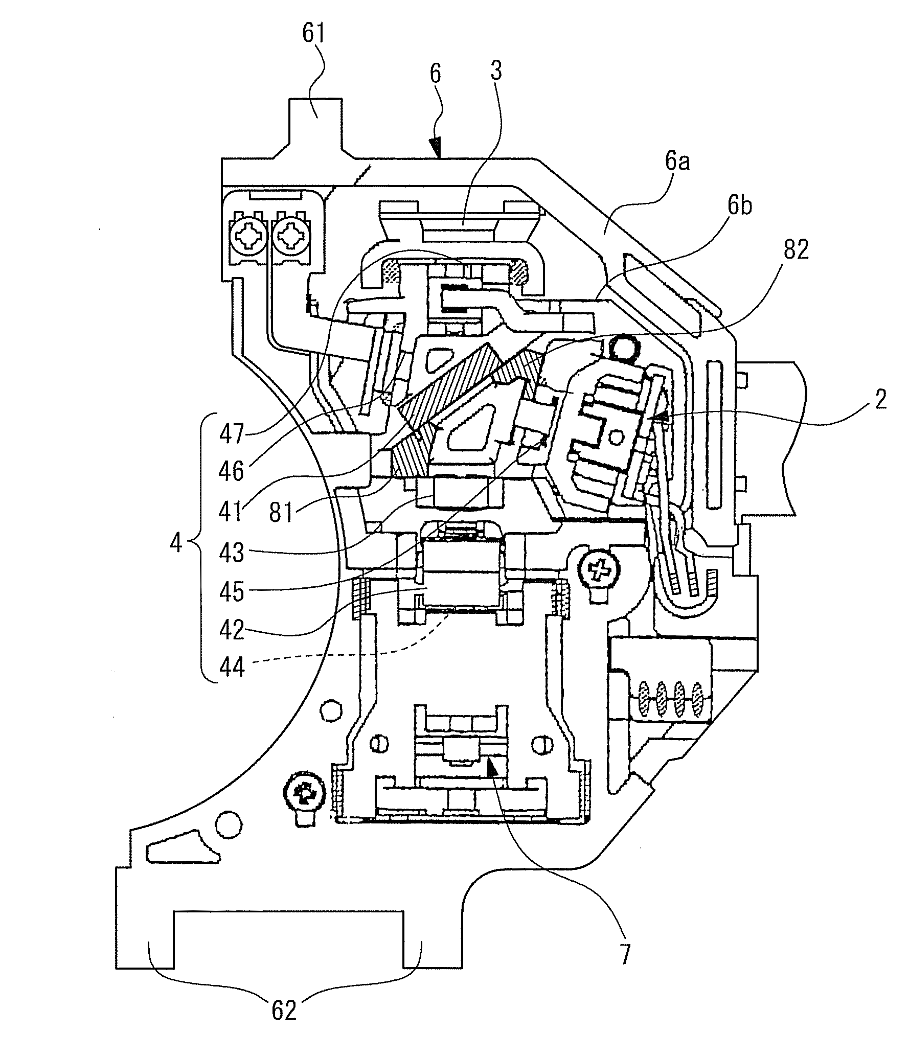
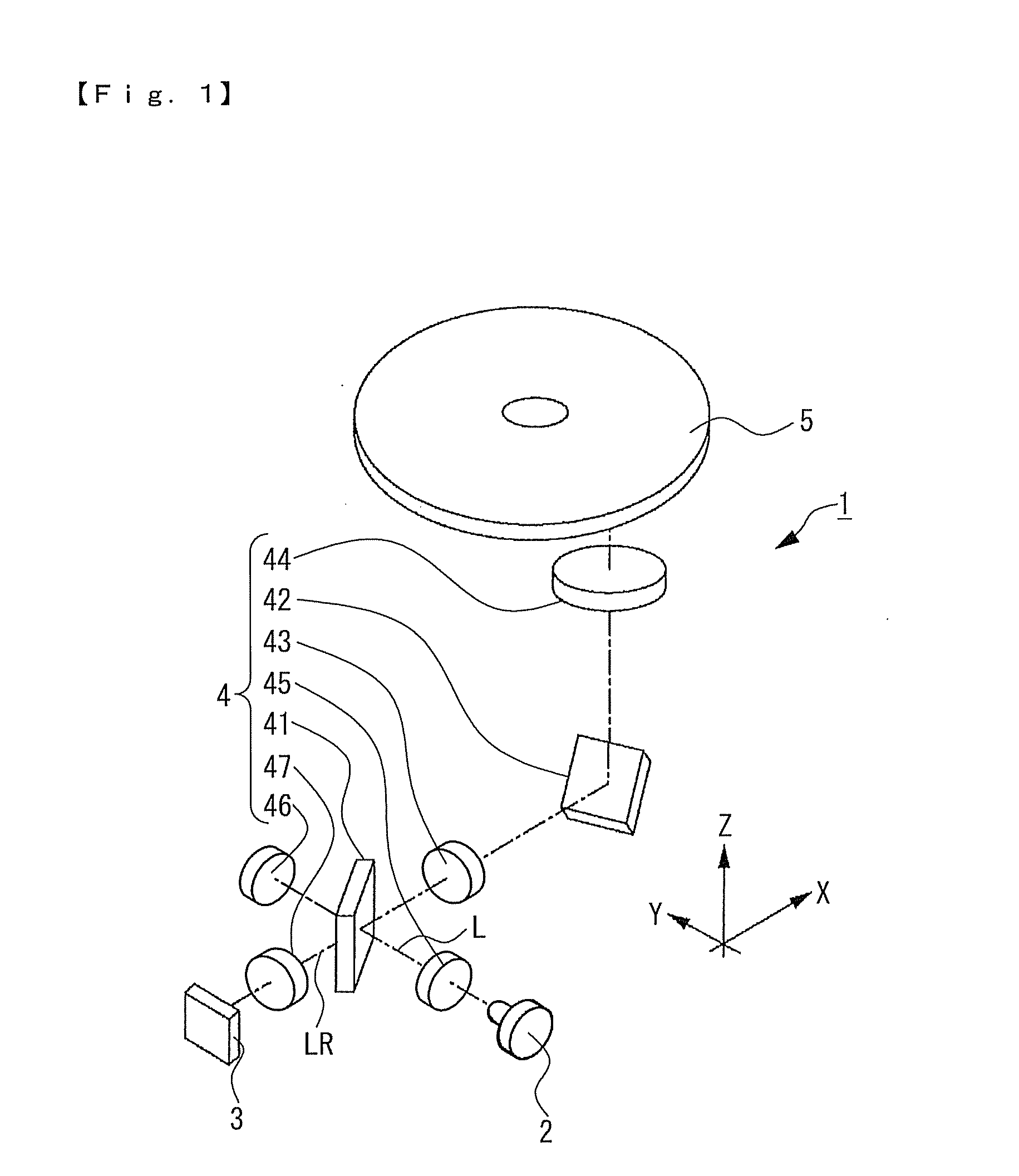
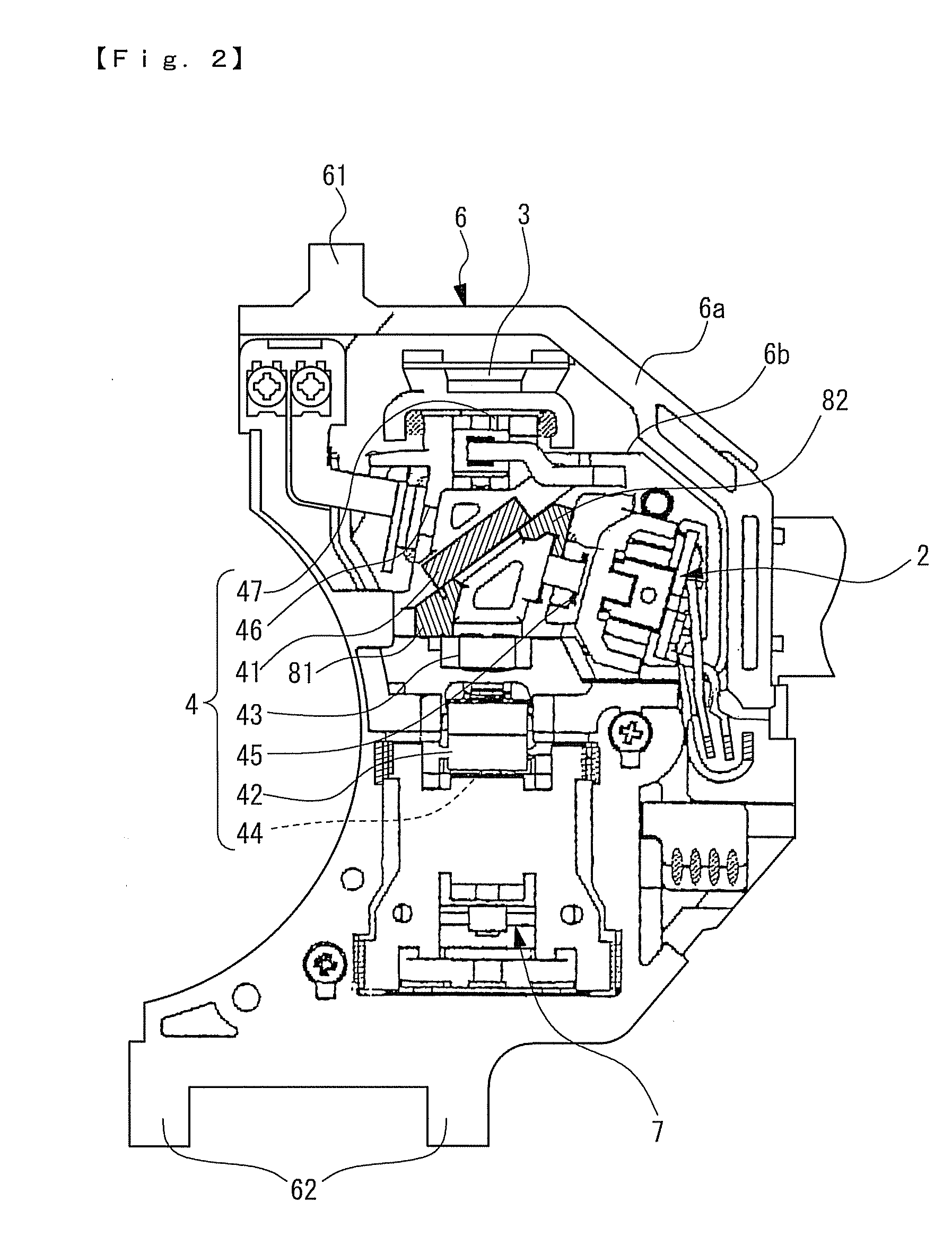
[0031]FIG. 1 is a schematic structure view showing an optical system of an optical head device in accordance with a fixing structure of an optical element in accordance with an embodiment of the present invention. FIG. 2 is a bottom view showing an optical head device.

[0032]An optical head device 1 in accordance with an embodiment of the present invention is a two-wavelength optical head device in which a first laser beam (infrared light) with a wavelength of 650 nm band and a second laser beam with a wavelength of 780 nm band are used as a laser light source 2, and which is capable of recording and reproducing into and from a DVD system disk and a CD system disk. Therefore, the laser light source 2 used in the optical head device 1 is a twin laser light source which is provided with a laser diode of AlGaInP system for emitting the first laser beam and a laser d...


PUM


Abstract

A fixing structure of an optical element such as a half mirror may include an optical element, a fixing member such as a frame which is formed with a reference surface, a first adhesive and a second adhesive which are used to fix the optical element on the reference surface. The first adhesive is coated so as to extend over the reference surface and the optical element, and the second adhesive is coated at a position where separation of the optical element from the reference surface due to thermal expansion of the first adhesive is restricted. An exposed side of the first adhesive is preferably formed in an opposite direction to an exposed side of the second adhesive with respect to the reference surface.

Description

CROSS REFERENCE TO RELATED APPLICATION[0001]The present invention claims priority under 35 U.S.C. § 119 to Japanese Application No. 2007-40374 filed Feb. 21, 2007, which is incorporated herein by reference.FIELD OF THE INVENTION[0002]An embodiment of the present invention relates to a fixing structure of an optical element.BACKGROUND OF THE INVENTION[0003]For example, an optical head device includes an optical system for guiding an emitted light beam which is emitted from a laser light source to an objective lens, which converges the emitted light beam at a target position on a recording face of an optical disk such as a CD or a DVD, and for guiding a return light beam reflected by the optical disk to a light receiving element. Various optical elements structuring the optical system are fixed at prescribed positions of a fixing member such as a device frame with an adhesive.[0004]For example, in an optical head device and its manufacturing method described in Japanese Patent Laid-Op...

Claims


Application Information

Patent Timeline
IPC IPC(8): G02B5/08
CPCG02B7/182G02B27/646G11B2007/0006G11B7/22G11B7/1275
Inventor WADE, TATSUKIKASUGA, TAKAFUMI
Owner SANKYO SEIKI MFG CO LTD
Learn More