
Uplink frequency multiplexing system

a frequency multiplexing and antenna gain technology, applied in the field of satellite transponders, can solve the problems of multiple transponders and does not represent efficient or optimal use of satellite resources, and achieve the effect of improving antenna gain and merit g/

Inactive Publication Date: 2008-08-28
EUTELSAT
View PDF5 Cites 2 Cited by
  • Summary
  • Abstract
  • Description
  • Claims
  • Application Information

AI Technical Summary

Benefits of technology

[0005]The object of the present invention is to satisfy the connectivity requirements while maintaining efficient and optimal use of satellite resources, particularly of the high power section of the payload and the bandwidth occupancy, with no degradation of the satellite figure of merit over the uplink service areas.
[0010]The satellite transponder offers thus the possibility to multiplex signals uplinked from different service areas into a single transponder using a simple technique, with no degradation of the figure of merit over each uplink service area.
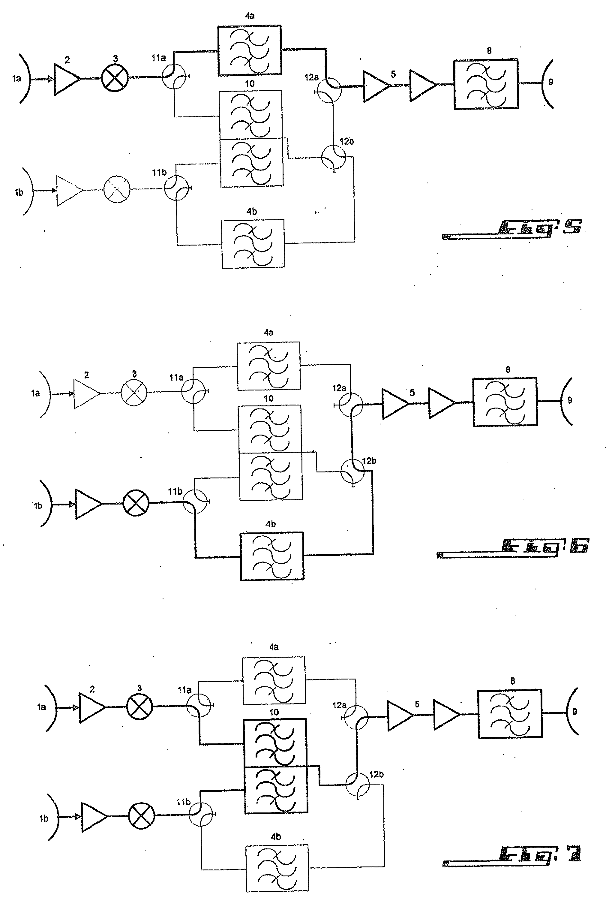
[0011]Particularly, the invention allows the system to be extended with different combinations of filters at the input multiplexer so that the passband associated to each uplink service area can be adjusted to fit varying commercial and marketing requirements throughout the satellite lifetime.
[0012]The system can also be employed to segment a given uplink service area into several sub areas, each sub area benefiting from an increased antenna gain and thus a better figure of merit G / T. The G / T can be adjusted to the actual needs of different parts of a given area, at no detriment to the power and frequency resources.

Problems solved by technology

The disadvantage of such a scheme is that if traffic exists from two or more service areas to a given service area, several transponders are required for connectivity purposes, even if the total required capacity is compatible with that of a single transponder.
This does not represent efficient or optimal use of the satellite resources, in terms of Radio Frequency resources (bandwidth) and power resources.

Method used


Image

  • Uplink frequency multiplexing system
  • Uplink frequency multiplexing system
  • Uplink frequency multiplexing system

Examples


Embodiment Construction

[0023]It is known that satellites include two subsystems, the platform and the payload. The platform supports the payload with the functions to constitute the structure including the development mechanisms for the antennae and solar arrays, the on board control system to ensure satellite autonomy, the electrical power system, the telecommand, telemetry and data handling system, the thermal control system and the attitude and orbital control system including the propulsion subsystem.

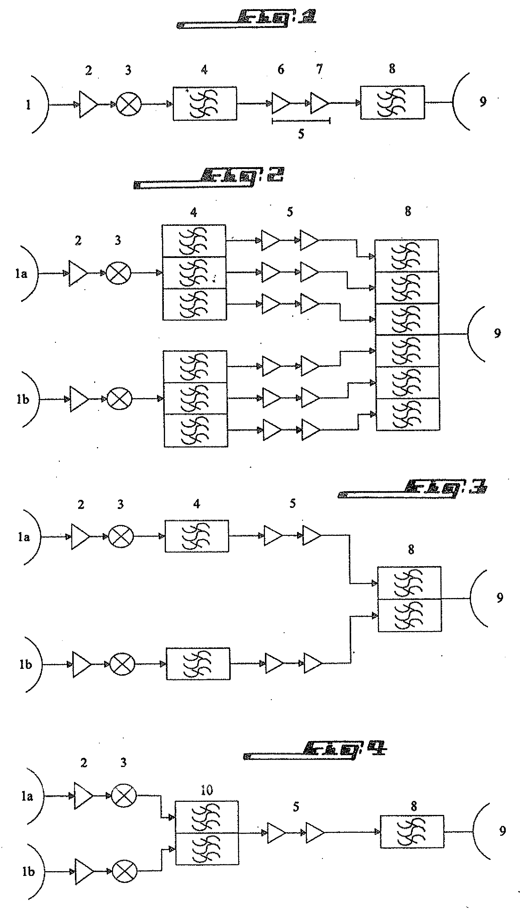
[0024]The payload is defined by the mission, which within the scope of this document shall be in general a communications mission. Typically a communications payload consists of a number of transponders the functional block diagram of which is given in FIG. 1.

[0025]In accordance to this figure, a transponder comprises an uplink antenna 1 with its associated service area, a low noise amplifier (LNA) 2, a converter 3, an input filter or demultiplexer 4, an amplification chain 5 including a channel amplifier...


PUM


Abstract

A satellite-borne transponder for two or more uplink service areas, includes uplink antennae, a low noise amplifier and a converter for each uplink antenna, input filters, amplification chains, each amplification chain including a channel amplifier, a high power amplifier, and an output filter, and a downlink antenna for an associated downlink service area. The transponder associates uplink antennae to an uplink service area, the number of antennae being determined by a preset Figure of Merit for each uplink service area. The transponder also includes at least one input multiplexer including a passband filter for each reception chains, each reception chain including an uplink antenna, a low noise amplifier, and a converter linked to the multiplexer.

Description

FIELD OF THE INVENTION [0001]The invention relates to a satellite transponder for two or more uplink service areas and a satellite communication system comprising such a transponder.[0002]In order to avoid any misunderstanding, it is specified that the present invention relates to a satellite-borne transponder for two or more uplink service areas and a satellite communication system comprising such a satellite-borne transponder, even if sometimes it is written “satellite transponder” or “transponder” only.BACKGROUND [0003]Traditionally, each transponder is associated with a single uplink service area and a single downlink service area. The disadvantage of such a scheme is that if traffic exists from two or more service areas to a given service area, several transponders are required for connectivity purposes, even if the total required capacity is compatible with that of a single transponder. This does not represent efficient or optimal use of the satellite resources, in terms of Ra...

Claims


Application Information

Patent Timeline
Patent Type & Authority Applications(United States)
IPC IPC(8): H04B7/185
CPCH04B7/18515
Inventor FENECH, HECTORLANCE, EMMANUEL
Owner EUTELSAT
Learn More