
Receiver with increased sensitivity

a receiver and sensitivity technology, applied in the field of receivers with increased sensitivity, can solve the problems of difficulty in distinguishing satellite signals, increasing the probability of receiving reflected signals, etc., and achieves the effects of increasing the sensitivity of the receiver, increasing the sensitivity of the embedded receiver, and increasing the antenna gain

Inactive Publication Date: 2006-11-16
INFINEON TECH AG
View PDF8 Cites 5 Cited by
  • Summary
  • Abstract
  • Description
  • Claims
  • Application Information

AI Technical Summary

Benefits of technology

[0006] One embodiment of the invention is directed to a receiver for a satellite based navigation system, wherein the receiver is configured for use in a portable unit. The receiver comprises an antenna with n number of sectors, wherein n is an integer, and n≧2. The receiver comprises a control device associated with the antenna. The receiver further comprises an orientation device connected to the control device, that is configured to determine a current orientation of the receiver. The control device dynamically controls that signals from each satellite are received by using the sector of the antenna with the highest gain in a current direction of the satellite, wherein the sector of the antenna is used based on the location of a satellite associated with satellite signal to be received and based on a current orientation of the receiver. The receiver according to the invention implies increased sensitivity of the receiver, and makes use of the increased antenna gain in each sector, compared to a traditional omni-directional antenna. Another advantage associated with this receiver is that multipath, i.e. reflected, satellite signals are attenuated.
[0007] In another embodiment, a further advantage is achieved when the orientation device comprises a compass and a tilt sensor configured to sense and determine a current tilt of the receiver.
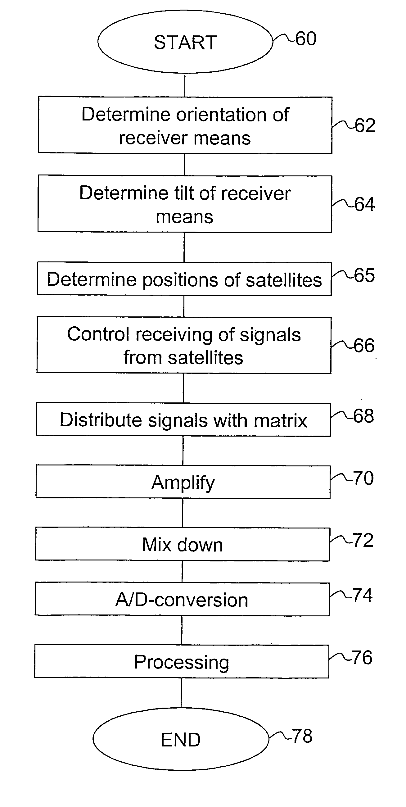
[0016] Furthermore, the invention is also directed to a method for increasing the sensitivity of a receiver for a satellite based navigation system, wherein the receiver is intended for use in a portable unit. The method comprises determining a current orientation of the receiver and determining a current position of each satellite with the aid of satellite navigation data. With the aid of a controller in the receiver, dynamically controlling the receiver so that signals from each satellite are received by using a particular sector out of n available sectors of an antenna, wherein the particular sector provides the highest gain in a current direction of the satellite. In one embodiment, the particular sector is selected based on the location of a satellite providing the received signals and on a current orientation of the receiver. The method according to one aspect of the invention increases the sensitivity of an embedded receiver, and makes use of the increased antenna gain in each sector, compared to a traditional omni-directional antenna. Another advantage with this method is that multipath effects, i.e. reflected satellite signals are attenuated.
[0025] In yet another embodiment, the invention provides at least one computer program product for increasing the sensitivity of a receiver for a satellite based navigation system, wherein the receiver is intended for use in a portable unit. The product(s) is / are directly loadable into the internal memory of at least one digital computer, and wherein the at least one computer program product comprises software code portions for performing the method according to the invention, when the at least one product is / are run on the at least one computer. The computer program product(s) according to the invention increase(s) the sensitivity of an embedded receiver, and make(s) use of the increased antenna gain in each sector, compared to a traditional omni-directional antenna. Another advantage with this / these computer program product(s) is that multipath effects, i.e. reflected, satellite signals are attenuated.

Problems solved by technology

A drawback in using such an antenna is that the use of an omni-directional antenna increases the probability of receiving reflected signals.
Another drawback with the use of an omni-directional antenna is that a lot of noise is received, resulting in difficulties in distinguishing the satellite signals.

Method used


Image

  • Receiver with increased sensitivity
  • Receiver with increased sensitivity
  • Receiver with increased sensitivity

Examples


Embodiment Construction

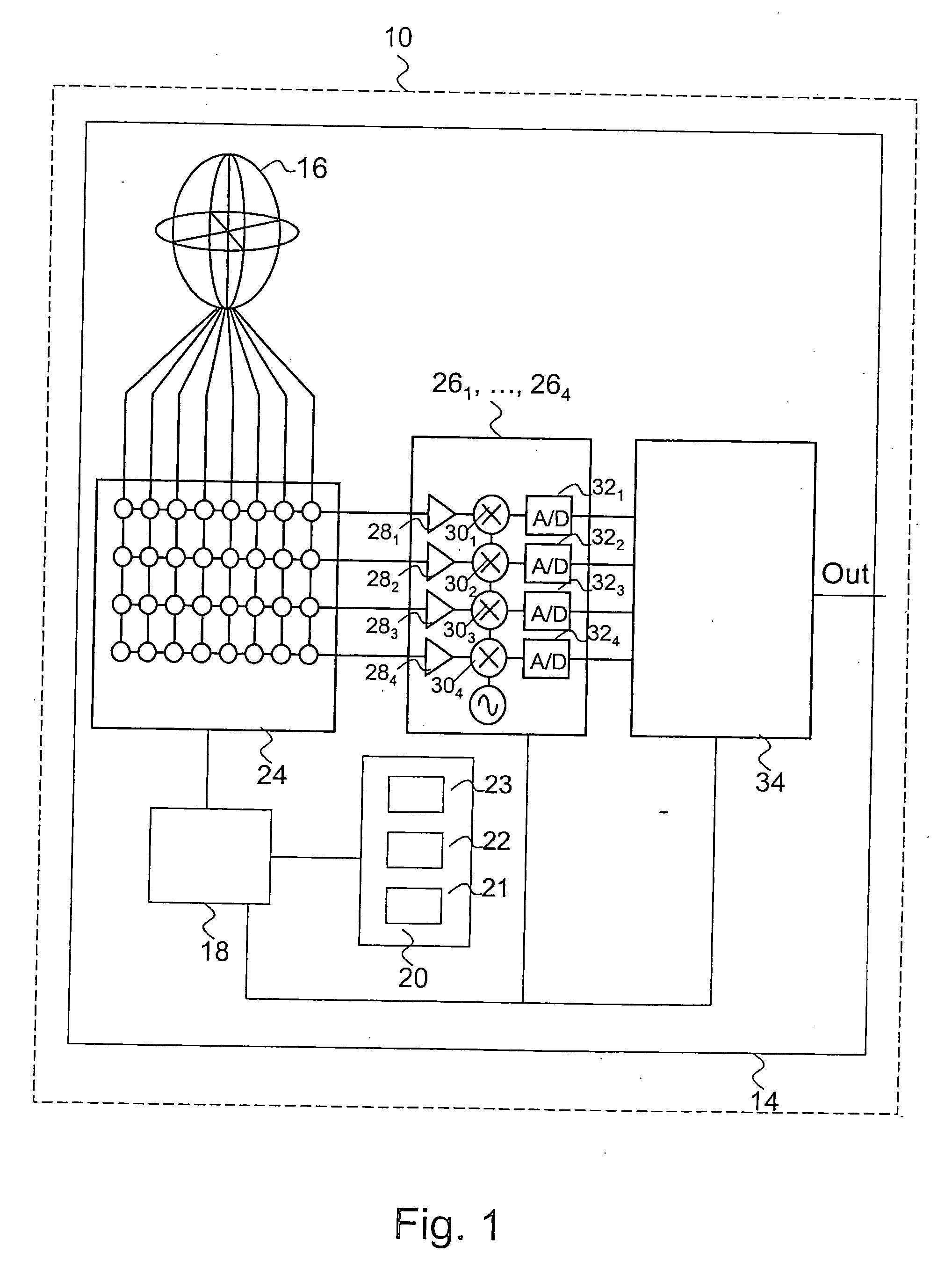
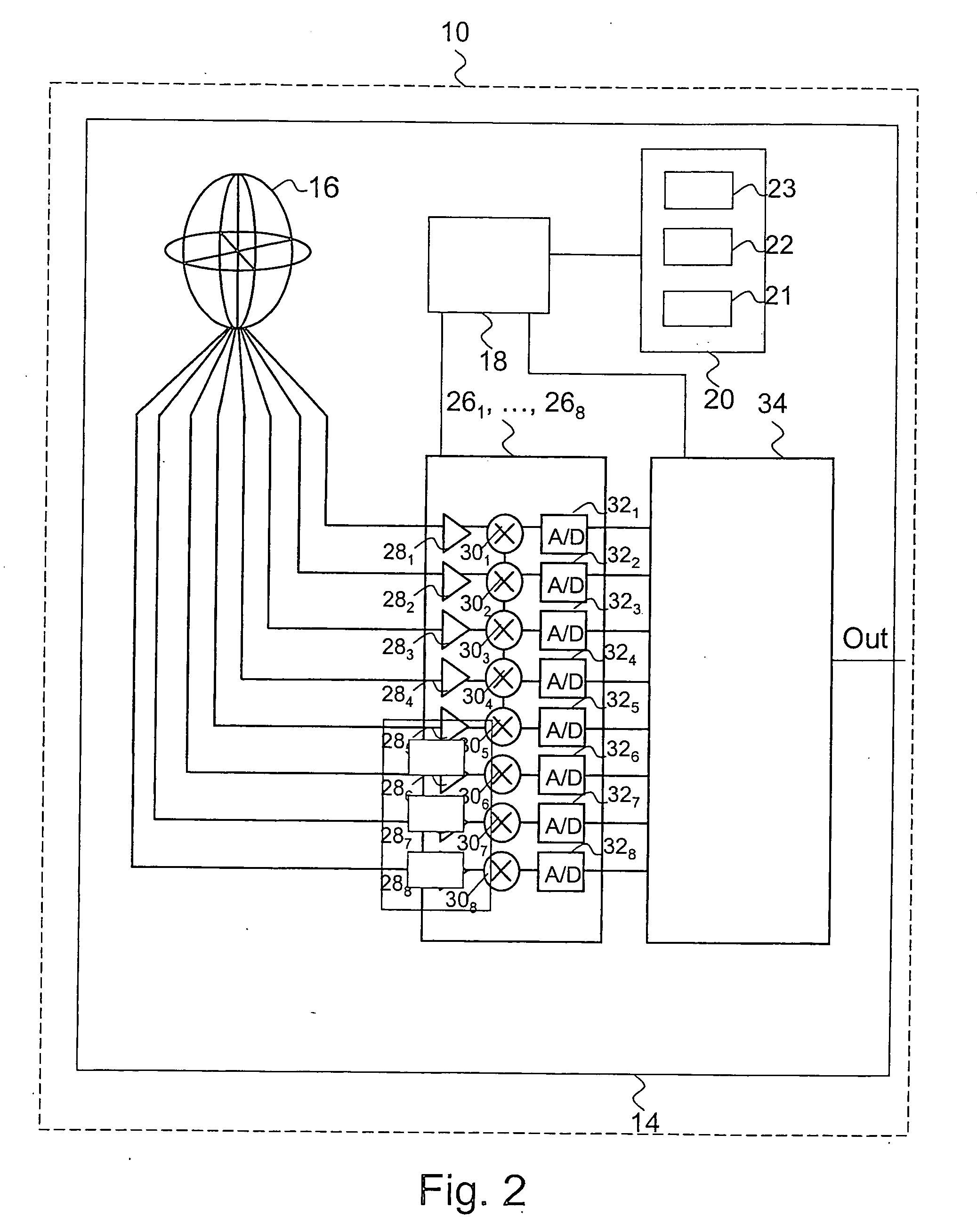
[0034]FIG. 1 illustrates a block diagram of a receiver 14 according to one embodiment of the invention which enables to increase the sensitivity of the receiver for a satellite based navigation system, wherein the receiver 14 is intended for use in a portable unit 10 as shown in FIG. 1. The receiver 14 comprises an antenna 16 with 8 antenna sectors. In FIG. 1 eight sectors are shown, but the general case comprises a number n of sectors, wherein n is an integer, and n≧2. The receiver 14 also comprises a switch matrix 24 connected to the 8 antenna sectors of the antenna 16. The switch matrix 24 shown in FIG. 1 has 8 inputs and four outputs. Generally, the switch matrix 24 comprises n inputs, and m outputs, wherein m is an integer, and m14 also comprises a control device 18 connected to four RF digitizer channels 261, . . . , 264, and to a processor 34. Also connected to the control device 18 is an orientation device 20 configured to determine a current orientation of the receiver 14. ...


PUM


Abstract

The invention relates to a receiver for a satellite based navigation system. The receiver comprises an antenna with multiple sectors, a controller associated with the antenna, and an orientation device connected to the controller. The invention determines a current orientation of the receiver, and dynamically controls the system so that signals from each satellite are received by using the sector of the antenna with the highest gain in the current direction of the satellite, in order to increase the sensitivity of the receiver.

Description

REFERENCE TO RELATED APPLICATIONS [0001] This application claims the benefit of the priority date of European application EP 05 008 804.6, filed on Apr. 21, 2005, the contents of which are herein incorporated by reference in their entirety. FIELD OF THE INVENTION [0002] The present invention relates to a receiver for a satellite based navigation system, and to a method for increasing the sensitivity of a receiver for a satellite based navigation system. BACKGROUND OF THE INVENTION [0003] Today it is common practice to have a portable unit with a receiver for a satellite based navigation system to be able to determine a current position of the portable unit. This portable unit comprises an omni-directional antenna to receive the signals from the satellites. The antenna usually used in this context is an antenna with only one antenna lobe. One known antenna with only one antenna lobe is a patch antenna with a semispherical antenna lobe. [0004] A drawback in using such an antenna is th...

Claims


Application Information

Patent Timeline
IPC IPC(8): G01S5/14H01Q3/00H04B7/185G01S19/28G01S19/22G01S19/36
CPCG01S19/22G01S19/36G01S19/28
Inventor NYLEN, TOMAS
Owner INFINEON TECH AG
Learn More