
Unbiased code phase discriminator

a phase discriminator and code technology, applied in the field of communication, timing or positioning devices, can solve the problems of large 0.4 m range error, and achieve the effect of eliminating or substantially reducing errors caused by multipaths and eliminating phase biases

Active Publication Date: 2008-08-28
HEMISPHERE GNSS
View PDF100 Cites 29 Cited by
  • Summary
  • Abstract
  • Description
  • Claims
  • Application Information

AI Technical Summary

Benefits of technology

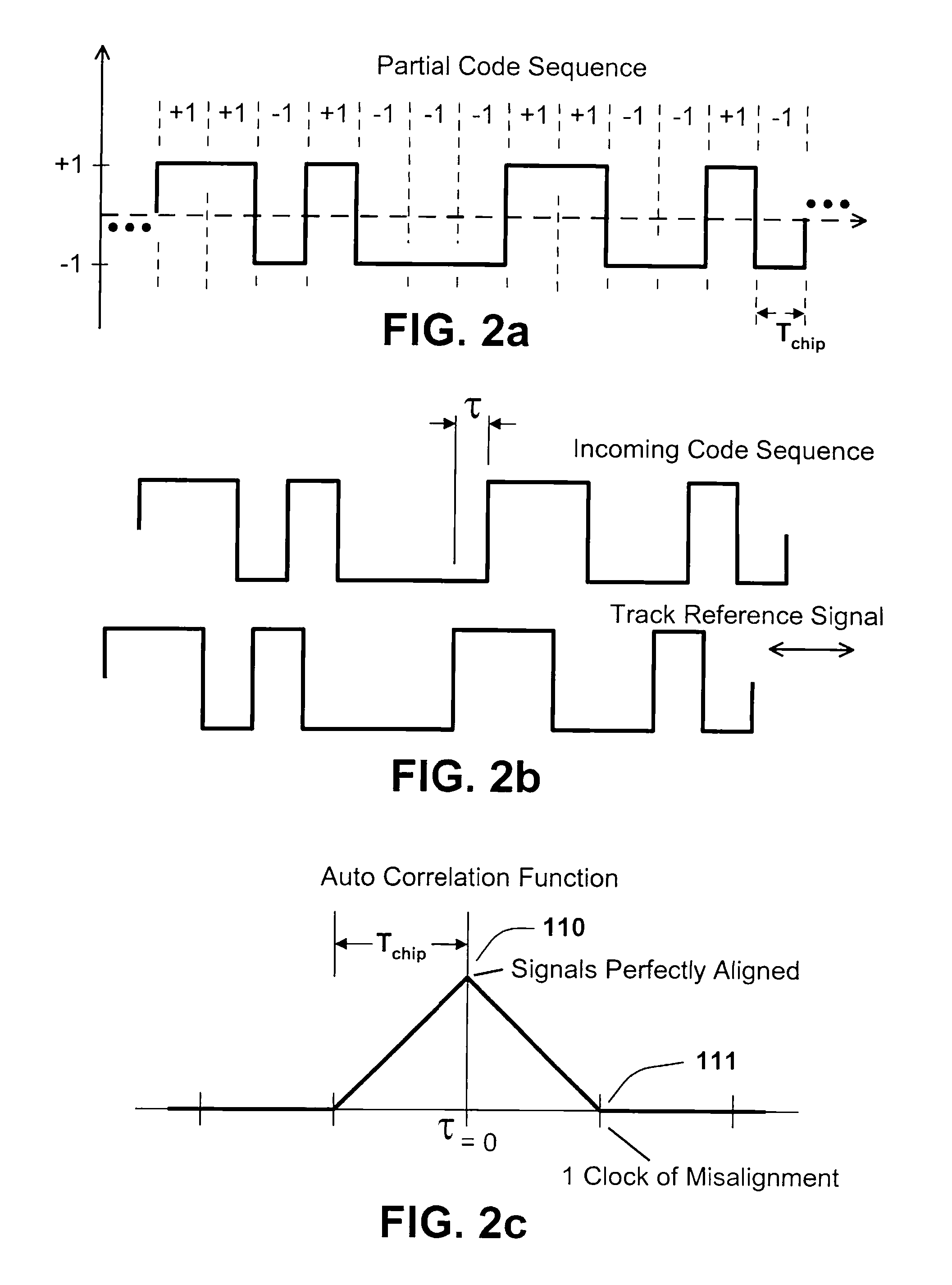
[0012]A feedback control law steers a reference phase that tracks the phase of a received code sequence. The reference phase clocks a track-reference signal consisting of a two separate series of correlation kernels, one that operates on code transitions (a transition meaning a change in sign from one code chip to the next) and one that operates on non-transitions (a non-transition meaning that the sign of two adjacent chips remains the same). The correlation kernels define regions of support over which data from the incoming signal is captured, possibly inverted (and possibly scaled), and then accumulated. The accumulations are correlation outputs that, when properly combined, taking into account the number of transitions and non-transitions, form a correlative phase discriminator. The phase discriminator provides a measure of phase tracking error that is made available to a feedback control loop that aligns the reference phase to the incoming code phase. The correlation kernels are designed in such a manner that errors caused by multipath are eliminated or substantially reduced. Furthermore, the areas of the correlation kernels are balanced across level-transitions of a code and non-transitions to eliminate phase biases when tracking specific satellites. Extra care must be taken to balance the correlation kernels in this manner due to a little known aspect of GPS C / A codes. Specifically, not all C / A codes have the same ratio of level-transitions to non-transitions as has been assumed in prior art.

Problems solved by technology

Therefore, even a small 0.5° phase error corresponds to a large 0.4 m range error.

Method used


Image

  • Unbiased code phase discriminator
  • Unbiased code phase discriminator
  • Unbiased code phase discriminator

Examples


Embodiment Construction

1. Introduction

[0051]As required, detailed embodiments and / or aspects of the present invention are disclosed herein; however, it is to be understood that the disclosed embodiments / aspects are merely exemplary of the invention, which may be embodied in various forms. Therefore, specific structural and functional details disclosed herein are not to be interpreted as limiting, but merely as a basis for the claims and as a representative basis for teaching one skilled in the art to variously employ the present invention in virtually any appropriately detailed structure.

[0052]FIG. 1 illustrates the three primary components of a code tracking loop: the phase discriminator 120, the loop filter 121 and the Numerically Controlled Oscillator (NCO) 122. The phase discriminator 120 generates an output error signal 123 proportional to the phase difference between the incoming (measured) signal to be tracked 124 and the current phase estimate 125. The error signal 123 is filtered by the loop filt...


PUM


Abstract

A feedback control law steers a reference phase that tracks the phase of a received code sequence. The reference phase clocks a track-reference signal consisting of a series of correlation kernels, over which data is extracted and then summed in various combinations. The correlation kernels are designed in such a manner that errors caused by multipath are eliminated or substantially reduced. Furthermore, the areas of the correlation kernels are balanced across level-transitions of a code and non-transitions to eliminate phase biases when tracking specific satellites. Extra care must be taken to balance the correlation kernels in this manner due to a little known aspect of GPS C / A codes. Specifically, not all C / A codes have the same ratio of level-transitions to non-transitions as has been assumed in prior art.

Description

CROSS-REFERENCE TO RELATED APPLICATION[0001]This application claims priority in U.S. Provisional Patent Application No. 60 / 891,906, filed Feb. 27, 2007, which is incorporated herein by reference.BACKGROUND OF THE INVENTION[0002]1. Field of the Invention[0003]The present invention relates generally to communication, timing, or positioning devices that receive signals containing, encoded within, a known sequence positive and negative symbols of unknown phase, and particularly to devices that achieve reduction in errors resulting from multipath.[0004]The invention discloses a method to produce a track reference signal, that when correlated against a code signal, produces a correlative-phase-discriminator that can act as a measure of the offset of the track reference signal relative to the code signal.[0005]2. Description of the Related Art[0006]Precise phase estimation is required by ranging and coherent communications systems. Existing ranging systems include Global Navigation Satelli...

Claims


Application Information

Patent Timeline
Patent Type & Authority Applications(United States)
IPC IPC(8): H04B1/707G06F17/15
CPCG01S19/29H04B2201/70715H04B1/7085
Inventor WHITEHEAD, MICHAEL L.MILLER, STEVE R.
Owner HEMISPHERE GNSS
Learn More