
Structure including via having refractory metal collar at copper wire and dielectric layer liner-less interface and related method

a technology of dielectric layer and dielectric wire, which is applied in the direction of electrical apparatus, semiconductor devices, semiconductor/solid-state device details, etc., can solve the problems of early failure, significant reduction of the current limit of the product chip, etc., and achieve the effect of preventing the voiding of the slit, and improving the interfa

Inactive Publication Date: 2008-08-28
TAIWAN SEMICON MFG CO LTD
View PDF15 Cites 21 Cited by
  • Summary
  • Abstract
  • Description
  • Claims
  • Application Information

AI Technical Summary

Benefits of technology

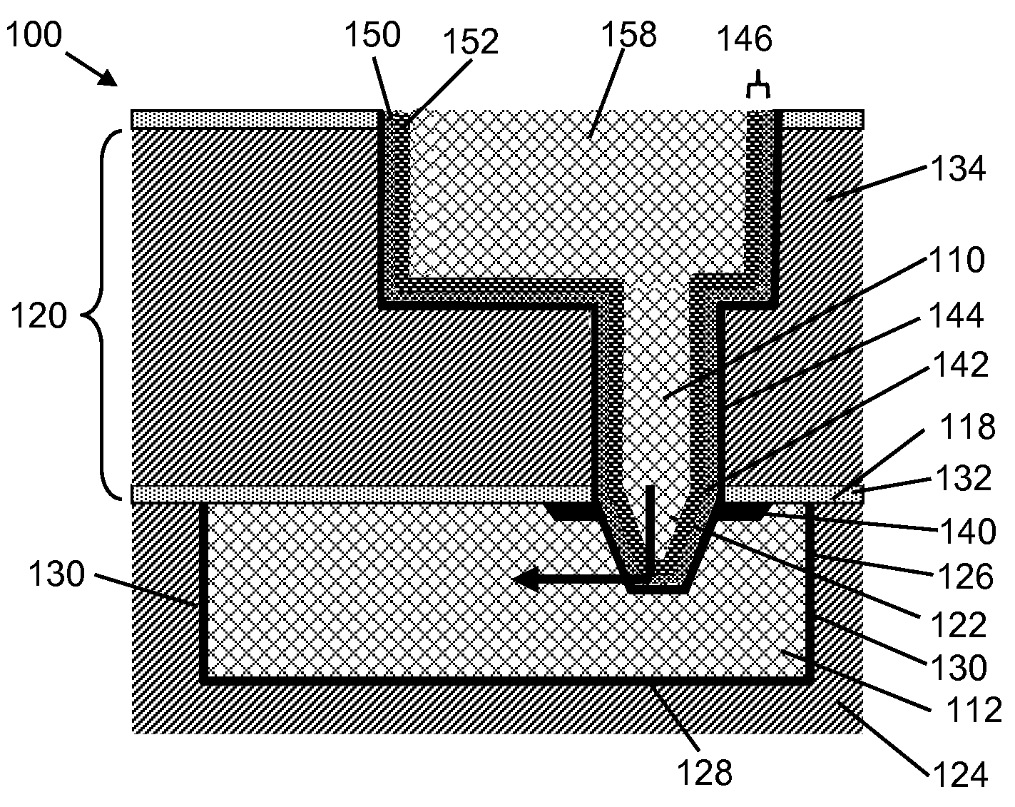
[0005]Structures including a refractory metal collar at a metal wire and dielectric layer liner-less interface, and a related method, are disclosed. In one embodiment, a structure includes a copper wire having a liner-less interface with a dielectric layer thereabove; a via extending upwardly from the copper wire through the dielectric layer, and a refractory metal collar extending from a side of the via and partially along the liner-less interface. Refractory metal collar prevents electromigration induced slit voiding by improving the interface around the via, and prevents void nucleation from occurring near the via. Also, the refractory metal collar provides electrical redundancy in the presence of voids around the via and dielectric layer liner-less interface.

Problems solved by technology

Early EM induced failure, in particular, significantly reduces the projected current limit of product chip under operating conditions.
It is well known that this slit void may cause very early fails under electromigration conditions during circuit operation, since it does not take much time to form such a small void.

Method used


Image

  • Structure including via having refractory metal collar at copper wire and dielectric layer liner-less interface and related method
  • Structure including via having refractory metal collar at copper wire and dielectric layer liner-less interface and related method
  • Structure including via having refractory metal collar at copper wire and dielectric layer liner-less interface and related method

Examples


Embodiment Construction

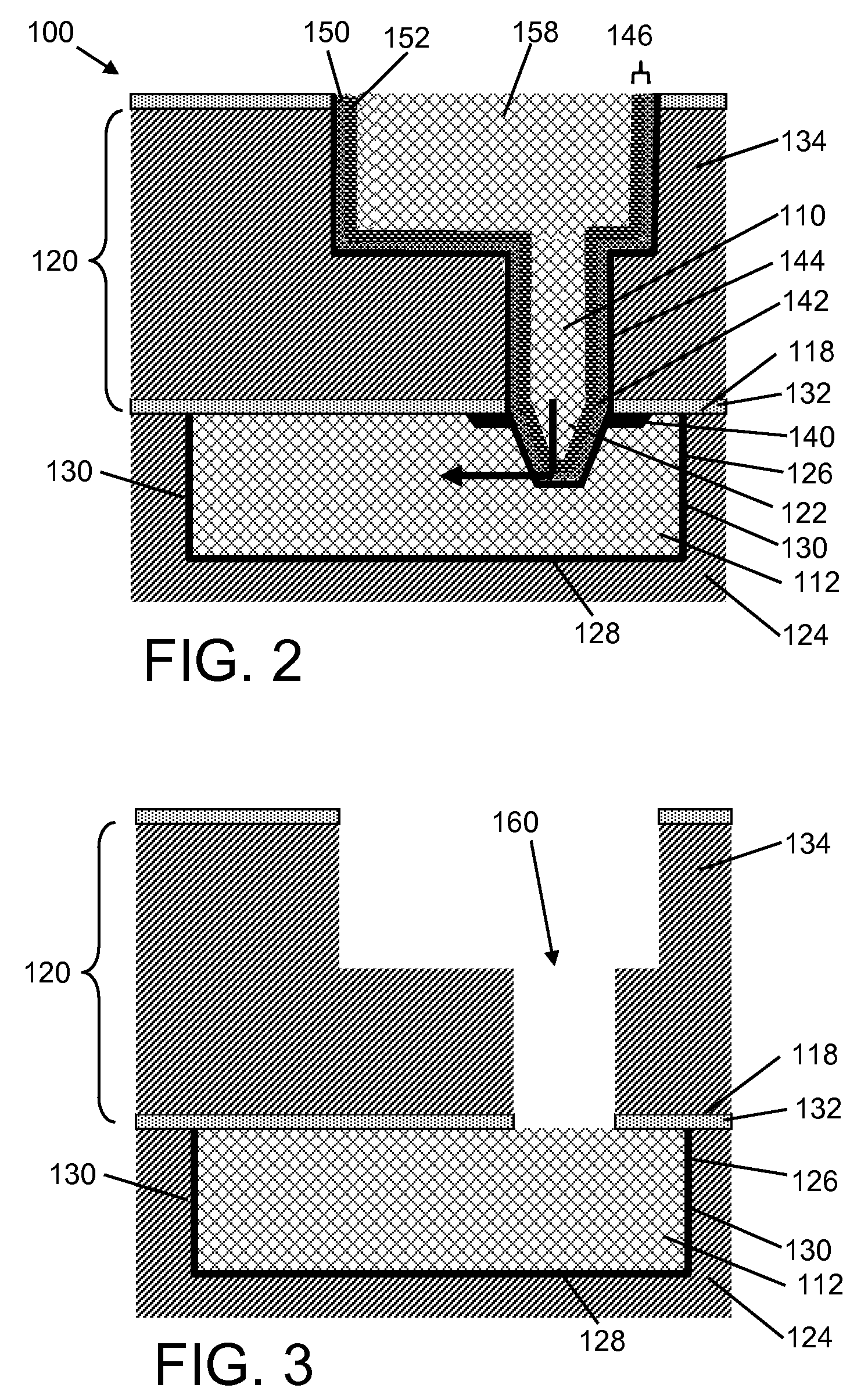
[0015]FIG. 2 shows a structure 100 according to embodiments of the disclosure. Structure 100 includes a via 110 extending upwardly from a metal wire 112, e.g., copper, through a dielectric layer 120. In one embodiment, via 110 includes a substantially frusto-conical portion 122 within metal wire 112. However, the teachings of the invention are not limited to that type of via. Metal wire 112 is positioned within another dielectric layer 124, and includes a liner 126 between metal wire 112 and dielectric layer 124. Liner 126 may include any now known or later developed metal diffusion barrier material, for example, tantalum, tantalum nitride, titanium, titanium nitride, tungsten, tungsten nitride, ruthenium, ruthenium nitride, etc. Note, however, liner 126 separates metal wire 112 and dielectric layer 124 along only a bottom 128 and sides 130 of metal wire 112. Accordingly, metal wire 112 includes a liner-less interface 118 with dielectric layer 120 thereabove.

[0016]Dielectric layer 1...


PUM

PropertyMeasurementUnit
refractoryaaaaaaaaaa
dielectricaaaaaaaaaa
dielectric constantaaaaaaaaaa

Abstract

Structures including a refractory metal collar at a copper wire and dielectric layer liner-less interface, and a related method, are disclosed. In one embodiment, a structure includes a copper wire having a liner-less interface with a dielectric layer thereabove; a via extending upwardly from the copper wire through the dielectric layer; and a refractory metal collar extending from a side of the via and partially along the liner-less interface. Refractory metal collar prevents electromigration induced slit voiding by improving the interface around the via, and prevents void nucleation from occurring near the via. Also, the refractory metal collar provides electrical redundancy in the presence of voids around the via and dielectric layer liner-less interface.

Description

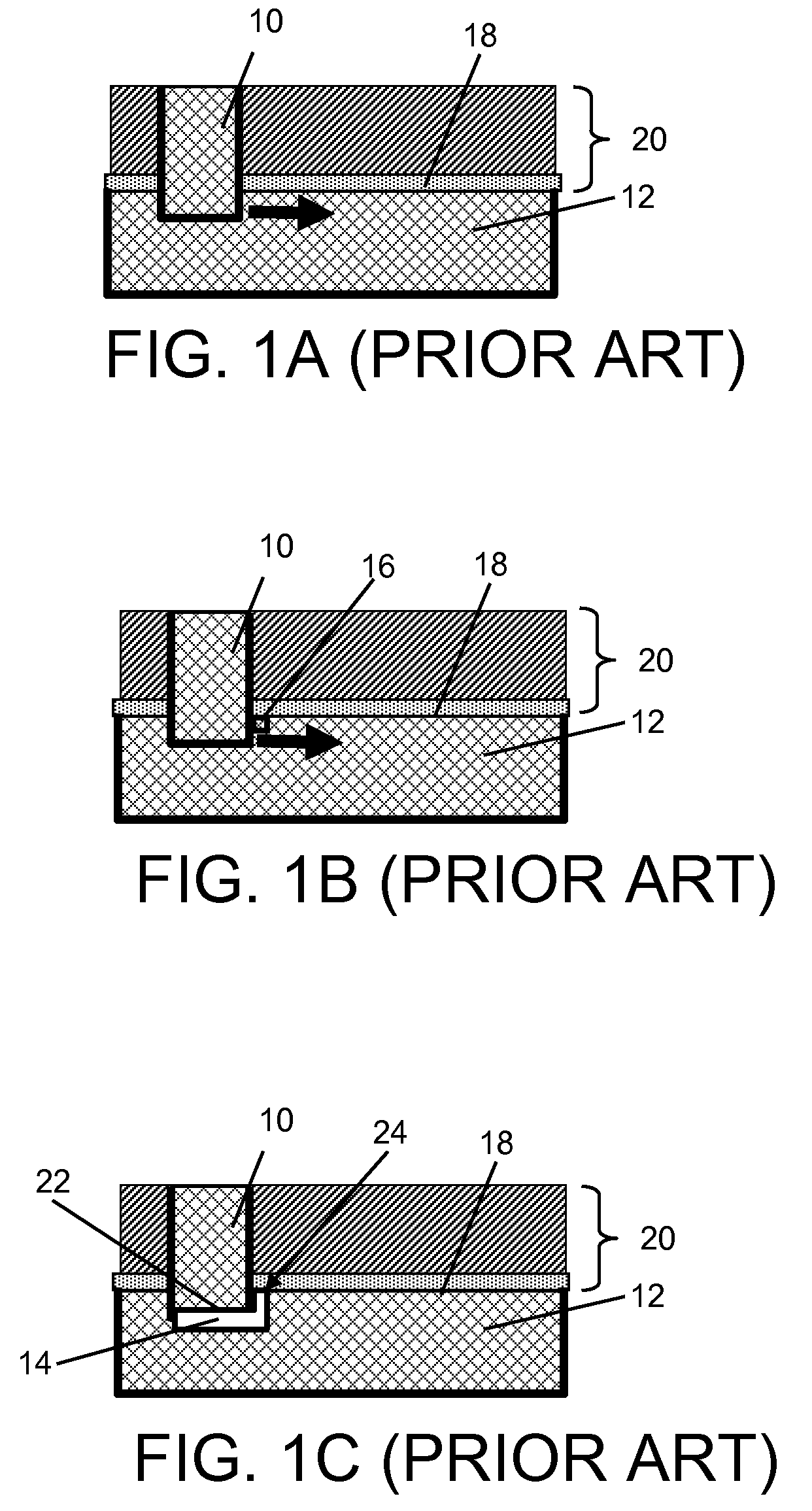
BACKGROUND[0001]1. Technical Field[0002]The disclosure relates generally to integrated circuit (IC) chip fabrication, and more particularly, to structures including a via having a refractory metal collar at a copper wire and dielectric layer liner-less interface, and a related method.[0003]2. Background Art[0004]In the integrated circuit (IC) chip fabrication industry, electromigration (EM) induced failure is a major concern for advanced back-end-of-line (BEOL) technology. Early EM induced failure, in particular, significantly reduces the projected current limit of product chip under operating conditions. One type of EM induced failure is referred to as “line-depletion.” As shown in FIGS. 1A-C, line-depletion EM includes electron current flowing from an upwardly extending via 10 down into a metal wire 12 below. As electron current flows, atoms move causing “slit void” failures 14 (FIG. 1C) initiating, for example, at a site 16 (FIG. 1B) between via 10 and a liner-less interface 18 b...

Claims


Application Information

Patent Timeline
Patent Type & Authority Applications(United States)
IPC IPC(8): H01L23/48H01L21/4763
CPCH01L21/76805H01L21/76814H01L21/76843H01L21/76849H01L23/53223H01L23/53238H01L2924/0002H01L23/5329H01L23/53295H01L2924/00
Inventor EDELSTEIN, DANIEL C.NOGAMI, TAKESHIWANG, PING-CHUANWANG, YUN-YUYANG, CHIH-CHAO
Owner TAIWAN SEMICON MFG CO LTD
Learn More