
Car side mirror equipped with thermal infrared camera

Inactive Publication Date: 2008-08-28
HANVISION
View PDF6 Cites 26 Cited by
  • Summary
  • Abstract
  • Description
  • Claims
  • Application Information

AI Technical Summary

Benefits of technology

[0014]By doing so, the car side mirror equipped with the thermal infrared camera according to the present invention can be easily installed separately and can transmit video information to a display device inside a car using radio communication technology such as Bluetooth, so that separate wiring work is not required, and thus the mounting thereof is simplified, thereby considerably reducing expenses for the installation of a thermal infrared camera device.
[0016]Another object of the present invention is to provide a car side mirror equipped with a thermal infrared camera, in which, in order to prevent the theft of the car side mirror, an encryption technique is applied to a thermal infrared camera device and a display device inside a car, and the operation of the thermal infrared camera device is prevented by preventing video signals and command signals from being normally transmitted in the case where the side mirror equipped with the thermal infrared camera is separated from the car and is installed in another car, thereby reducing the likelihood of theft of the car side mirror.
[0023]The radio communication is realized in such a way as to install an antenna on one surface of the side mirror in the form of a microstrip antenna and enable the antenna to communicate with a display device (which is used as a representative of various information display devices) inside the car, thus minimizing aerial resistance and manufacturing costs.

Problems solved by technology

Meanwhile, when radio communication is expensive or is difficult to perform, a car side mirror integrated with a thermal infrared camera device, which is capable of transmitting video information and command information via an existing signal line, is provided.

Method used


Image

  • Car side mirror equipped with thermal infrared camera
  • Car side mirror equipped with thermal infrared camera
  • Car side mirror equipped with thermal infrared camera

Examples


Embodiment Construction

[0038]Reference now should be made to the drawings, in which the same reference numerals are used throughout the different drawings to designate the same or similar components.

[0039]Preferred embodiments of the present invention are described in detail below with reference to the accompanying drawings.

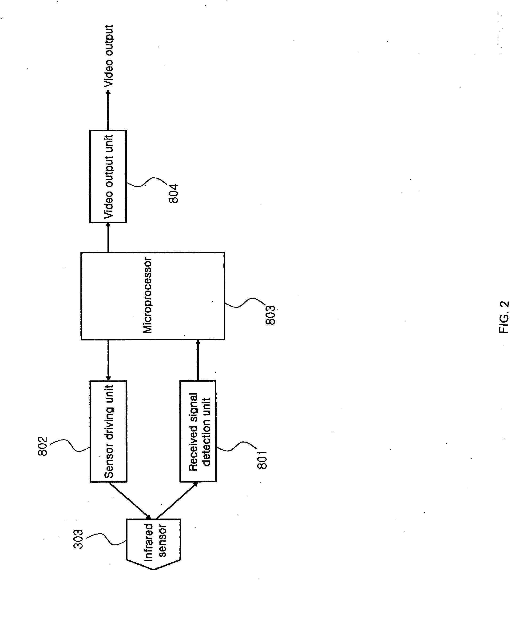
[0040]FIG. 3 is a diagram showing the construction of a car side mirror equipped with a thermal infrared camera device according to the present invention, and FIG. 4 is a block diagram showing the thermal infrared camera device of FIG. 3.

[0041]As shown in FIGS. 3 and 4, in each of the car side mirrors 400a and 400b equipped with thermal infrared camera devices according to the present invention, a thermal infrared camera 402 is mounted on the front surface of a side mirror member 404, and a microstrip antenna 401 is mounted inside the side mirror member 404. Furthermore, an opening 403 is formed through the side mirror member 404, and dissipates heat that is generated in the heat dissi...


PUM


Abstract

Disclosed herein is a car side mirror equipped with a thermal infrared camera. The car side mirror includes a thermal infrared camera device, a video signal transmission device, a power unit. Associated with the side mirror device is a display device inside the car. The thermal infrared camera device includes a thermal image sensor for receiving infrared signals, an electronic circuit for determining whether an obstacle exists in front of a car, and containing an individual Identification (ID), and a video output unit for converting output signals into video signals. The thermal infrared camera device photographs one or more objects in a desired direction. The video signal transmission device transmits the video signals to a display device. The power unit supplies power to the thermal infrared camera device and the video signal transmission device. The display device identifies the individual ID of the thermal infrared camera and then receives the video signals.

Description

BACKGROUND OF THE INVENTION[0001]1. Field of the Invention[0002]The present invention relates generally to a car side mirror equipped with a thermal infrared camera and, more particularly, to a car side mirror in which a small thermal infrared camera device and a microstrip antenna are installed, thereby enabling the monitoring of objects in front of the car.[0003]2. Description of the Related Art[0004]Generally, people make driving decisions while viewing the road ahead using the naked eye with the assistance of external illumination, such as ambient light or the light from headlights. However, when driving in fog or at night, the risk of a traffic accident is increased compared to a well lit roadway, since it can be difficult to see and recognize objects with sufficient time for drivers using only the naked eye.[0005]Accordingly, the use of electronic equipment to assist in and to augment the driver's vision capabilities in cases of poor visibility is desirable.Thermal infrared ca...

Claims


Application Information

Patent Timeline
IPC IPC(8): G01J5/04
CPCB60R1/00B60R1/12B60R2001/1253B60R2300/105G01J2005/0077B60R2300/8093G01J1/02G01J1/0252G01J5/061B60R2300/107B60R1/28B60R1/31B60R1/30B60R1/06B60R1/08
Inventor YOO, SANG KEUN
Owner HANVISION
Learn More