Load optimized redundant flight control surface actuation system and method

a flight control and redundant technology, applied in the field of flight control systems, can solve the problems of composite surfaces that cannot be actuated electrically and hydraulically, composite surfaces that cannot be actuated in time,

Inactive Publication Date: 2008-08-28
HONEYWELL INT INC
View PDF19 Cites 23 Cited by
  • Summary
  • Abstract
  • Description
  • Claims
  • Application Information

AI Technical Summary

Benefits of technology

[0006]In one embodiment, and by way of example only, an aircraft flight control surface actuation system includes an electromechanical actuator assembly, a hydraulic actuator assembly, a hydraulic actuator control, and an electromechanical actuator control. The electromechanical actuator assembly is adapted to be selectively supplied with electrical current and, upon receipt of the electrical current, to supply a force. The hydraulic actuator assembly is adapted to selectively receive a supply of hydraulic fluid and, upon receipt of the hydraulic fluid, to supply a force. The hydraulic actuator control is adapted to receive a position command signal and is configured, in response thereto, to control the supply of hydraulic fluid to the hydraulic actuator assembly. The electromechanical actuator control is configured to determine whether the hydraulic actuator assembly is supplying an adequate amount of force and, based in part on this determination, to control the electrical current supplied to, and thus the force supplied by, the electromechanical actuator assembly.
[0007]In another exemplary embodiment, an aircraft includes a flight control surface, an electromechanical actuator assembly, a hydraulic actuator assembly, a hydraulic actuator control, and an electromechanical actuator control. The flight control surface is coupled to receive a force from one or more sources and is configured, upon receipt of the force, to move. The electromechanical actuator assembly is adapted to be selectively supplied with electrical current and, upon receipt of the electrical current, to supply a first force to the flight control surface. The hydraulic actuator assembly is adapted to selectively receive a supply of hydraulic fluid and, upon receipt of the hydraulic fluid, to supply a second force to the flight control surface. The hydraulic actuator control is adapted to receive a position command signal and is configured, in response thereto, to control the supply of hydraulic fluid to the hydraulic actuator assembly. The electromechanical actuator control is configured to determine whether the second force supplied by the hydraulic actuator assembly is an adequate amount of force and, based in part on this determination, to control the electrical current supplied to, and thus the first force supplied by, the electromechanical actuator assembly.
[0008]In yet another exemplary embodiment, a method of moving a flight control surface having a hydraulic actuator assembly and an electromechanical actuator assembly coupled thereto includes supplying a force to the flight control surface from the hydraulic actuator assembly, and supplying a force to the flight control surface from the electromechanical actuator assembly. A determination is made as to whether the hydraulic actuator assembly is supplying an adequate amount of force to the flight control surface. The force supplied from the electromechanical actuator assembly to the flight control surface is controlled based partially on the determination of whether the hydraulic actuator assembly is supplying sufficient force to the flight control surface.
[0009]Other independent features and advantages of the preferred flight control surface actuation system and method will become apparent from the following detailed description, taken in conjunction with the accompanying drawings which illustrate, by way of example, the principles of the invention.

Problems solved by technology

Though unlikely, it is postulated that a flight control surface actuator could become jammed, uncontrollably free, or otherwise inoperable.
While this would seemingly be a straightforward solution, it nonetheless can present certain drawbacks, particularly with the concurrent on-going move to implement composite surfaces.
More specifically, presently proposed composite surfaces can exhibit little ability to sink heat.
As a result, coupling electrically and hydraulically powered actuators to the same surface can present difficulties.
For example, using electrically and hydraulically powered actuators may result in increased weight as a result of the heat sinking that may be needed on the composite structure.

Method used


Image

  • Load optimized redundant flight control surface actuation system and method
  • Load optimized redundant flight control surface actuation system and method
  • Load optimized redundant flight control surface actuation system and method

Examples


Embodiment Construction

[0016]The following detailed description is merely exemplary in nature and is not intended to limit the invention or the application and uses of the invention. Furthermore, there is no intention to be bound by any theory presented in the preceding background or the following detailed description.

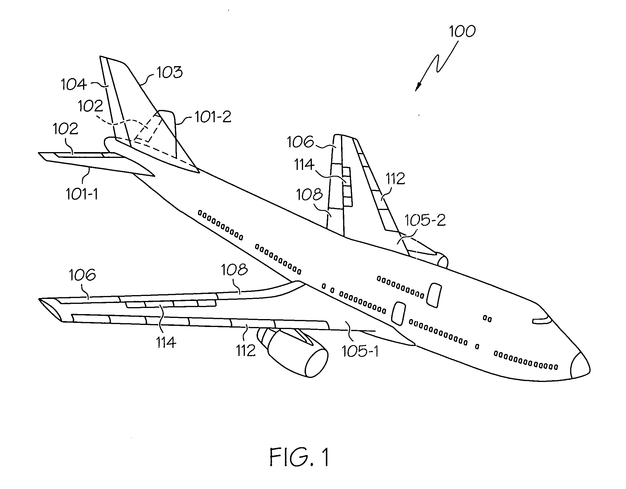
[0017]Turning first to FIG. 1, a perspective view of an exemplary aircraft is shown. In the illustrated embodiment, the aircraft 100 includes first and second horizontal stabilizers 101-1 and 101-2, respectively, a vertical stabilizer 103, and first and second wings 105-1 and 105-2, respectively. An elevator 102 is disposed on each horizontal stabilizer 101-1, 101-2, a rudder 104 is disposed on the vertical stabilizer 103, and an aileron 106 is disposed on each wing 105-1, 105-2. In addition, a plurality of flaps 108, slats 112, and spoilers 114 are disposed on each wing 105-1, 105-2. The elevators 102, the rudder 104, and the ailerons 106 are typically referred to as the primary flight cont...


PUM


Abstract

An aircraft flight surface control system and method simultaneously provides the benefits of both an active/active system architecture and in active/standby system architecture. The system is preferably implemented using hydraulic actuator assemblies and electromechanical actuator assemblies coupled to the same flight control surface. During normal system operations the electromechanical actuator assemblies are energized to supply a relatively minimal force to associated flight control surfaces. In effect, the electromechanical actuators, although energized, may be pulled along by the associated hydraulic actuator assemblies, until needed. Thus, the electromechanical actuator assemblies are controlled in a manner that closely resembles the active/standby architecture.

Description

TECHNICAL FIELD[0001]The present invention generally relates to aircraft flight control systems and, more particularly, an aircraft flight control system and method that simultaneously provides various benefits associated with both active / active redundancy architectures and active / standby redundancy architectures.BACKGROUND[0002]Aircraft typically include a plurality of flight control surfaces that, when controllably positioned, guide the movement of the aircraft from one destination to another. The number and type of flight control surfaces included in an aircraft may vary, but typically include both primary flight control surfaces and secondary flight control surfaces. The primary flight control surfaces are those that are used to control aircraft movement in the pitch, yaw, and roll axes, and the secondary flight control surfaces are those that are used to influence the lift or drag (or both) of the aircraft. Although some aircraft may include additional control surfaces, the pri...

Claims


Application Information

Patent Timeline
Patent Type & Authority Applications(United States)
IPC IPC(8): B64C13/24
CPCY02T50/44B64C13/42Y02T50/40
Inventor YOUNT, LARRY J.HANLON, CASEYJOHNSON, ANDY
Owner HONEYWELL INT INC
Why Eureka
Try Eureka