
Low-complexity scalable architecture for concatenation-assisted symbol-level combining

a concatenation-assisted symbol and low complexity technology, applied in the field of decoding a received signal vector, can solve the problems of not all sources of signal corruption are caused by deterministic sources, the receiver is unable to correctly reconstruct the transmitted information, and the signal is corrupted. the effect of reducing the complexity of the receiver

Active Publication Date: 2008-08-21
NXP USA INC
View PDF22 Cites 66 Cited by
  • Summary
  • Abstract
  • Description
  • Claims
  • Application Information

AI Technical Summary

Benefits of technology

[0014]In some embodiments of the invention, the N channel response matrices, also referred to as channel matrices, which define how each of the channels alter the transmitted signal in a noiseless scenario, are also concatenated into a single NNr×Nt matrix. The concatenated channel matrix may be used by a decoder (e.g., an ML decoder) to decode a combined received signal vector. In some embodiments, a preprocessor processes the concatenated channel response matrix, also called the concatenated channel matrix. Then, rather than directly decoding the concatenated NNr-dimensional received vector, the concatenated received vector is processed or equalized according to information obtained from preprocessing the concatenated channel matrix. The result of the equalization operation is a processed signal vector that may be decoded using the same decoder no matter how large or small N is. Thus, the complexity of the receiver may be drastically reduced.

Problems solved by technology

The medium, or media, between the transmitter and receiver, through which the information is sent, may corrupt the signal such that the receiver is unable to correctly reconstruct the transmitted information.
However, not all sources of signal corruption are caused from deterministic sources such as ISI.
Non-deterministic sources, such as noise sources, may also affect the signal.
Due to noise and other factors, signal processing techniques may not be entirely effective at eliminating adverse channel effects on their own.
If, after error detection, there are still errors present, the receiver will request a retransmission of that packet.
Therefore, the low redundancy code used for the first transmission of a packet has a high code rate, or throughput, but is less powerful at correcting errors.
However, due to system complexity, and in particular decoder complexity, many practical schemes only use data from a small, fixed number of transmissions.

Method used


Image

  • Low-complexity scalable architecture for concatenation-assisted symbol-level combining
  • Low-complexity scalable architecture for concatenation-assisted symbol-level combining
  • Low-complexity scalable architecture for concatenation-assisted symbol-level combining

Examples


Embodiment Construction

[0050]The disclosed invention provides a technique in a multiple-input multiple-output data transmission or storage system to decode a signal vector at a receiver, where the receiver may receive multiple signal vectors from the same transmitted signal vector.

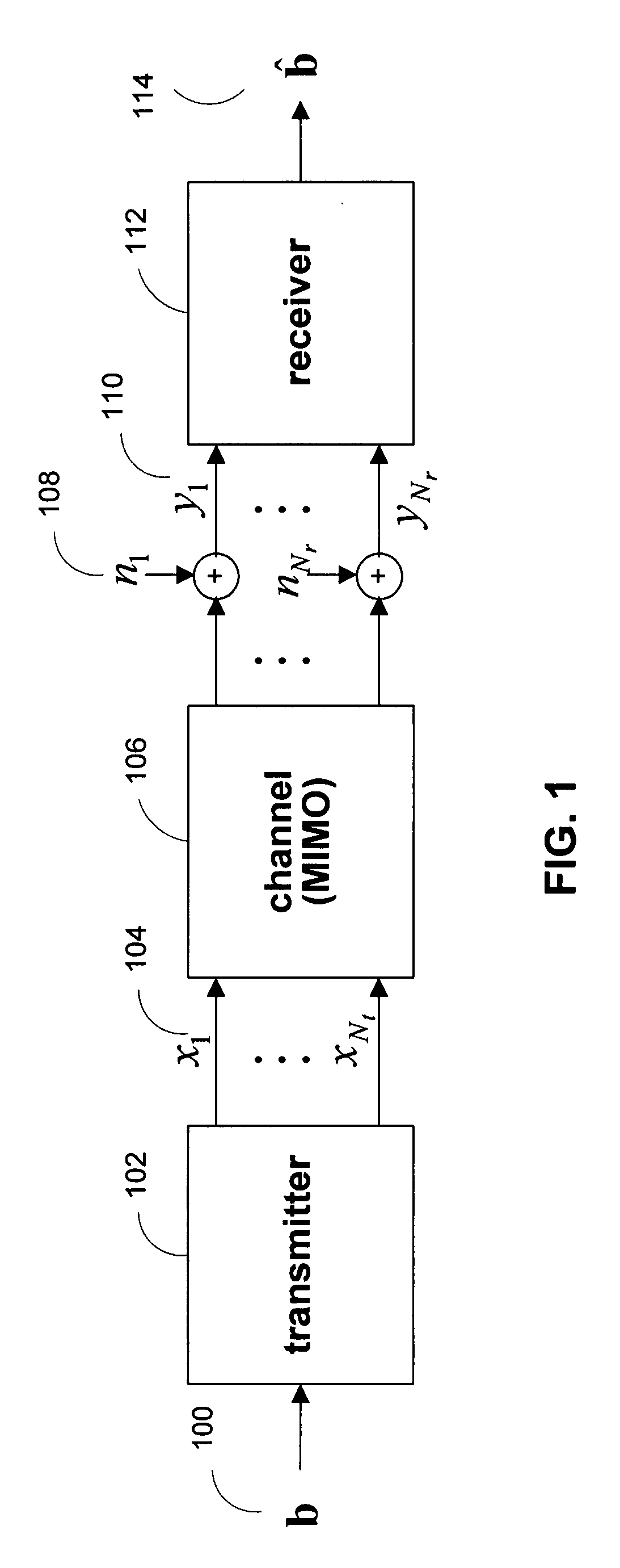
[0051]FIG. 1 shows an illustration of a basic data transmission or storage system in accordance with one embodiment of the present invention. Data, typically grouped into packets, is sent from transmitter 102 to receiver 112. During transmission, the signals may be altered by a transmission medium, represented by channel 106, and additive noise sources 108. Transmitter 102 has Nt outputs 104 and receiver 112 has Nr inputs 110, so channel 106 is modeled as a multiple-input multiple-output (MIMO) system with Nt inputs and Nr outputs. The Nt input and Nr output dimensions may be implemented using multiple time, frequency, or spatial dimensions, or any combination of such dimensions.

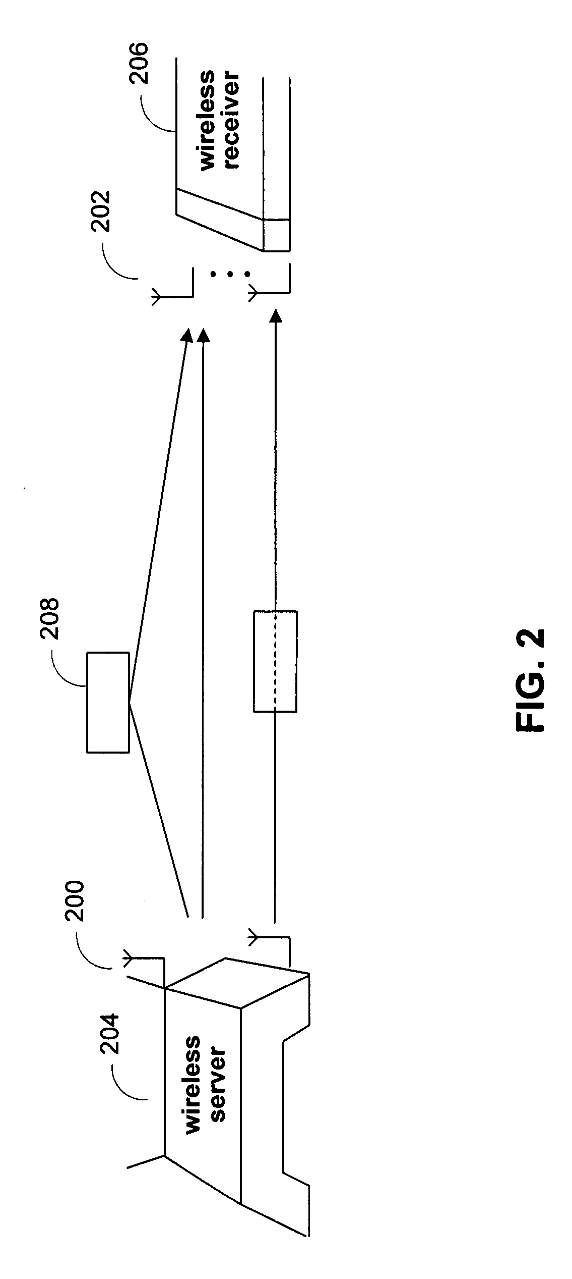
[0052]In one embodiment, FIG. 1 represents a wirel...


PUM


Abstract

Systems and methods are provided for decoding signal vectors in multiple-input multiple-output (MIMO) systems, where a receiver has received one or more signal vectors from the same transmitted vector. The receiver processes these received signal vectors one by one, and uses information from signal vectors that have already been processed to process the next signal vector. To process a current signal vector, the receiver concatenates the current signal vector with a previously processed signal vector. This concatenated signal vector is decoded using, for example, a maximum-likelihood (ML). To decode the concatenated signal vector, the ML decoder can use a concatenated channel matrix that includes a channel response matrix associated with the current signal vector and a processed version of previous channel response matrices.

Description

CROSS-REFERENCE TO RELATED APPLICATIONS[0001]This application claims the benefit under 35 U.S.C. §119(e) of U.S. Provisional Application No. 60 / 822,827, filed Aug. 18, 2006, which is incorporated herein by reference in its entirety.BACKGROUND OF THE INVENTION[0002]This invention relates to a technique for decoding a received signal vector in a multiple-input multiple-output (MIMO) data transmission or storage system, where the receiver may receive multiple instances of the same transmitted signal vector.[0003]In a data transmission or storage system, it is desirable for information, often grouped into packets, to be accurately received at a destination. A transmitter at or near the source sends the information provided by the source via a signal or signal vector. A receiver at or near the destination processes the signal sent by the transmitter. The medium, or media, between the transmitter and receiver, through which the information is sent, may corrupt the signal such that the rec...

Claims


Application Information

Patent Timeline
Patent Type & Authority Applications(United States)
IPC IPC(8): H04L27/28H04L5/04
CPCH04L1/0047H04L1/08H04L1/1812H04L2025/03426H04L25/0246H04L25/03331H04L2025/0342H04L25/0204
Inventor SONG, LEILEILEE, JUNGWONJANG, WOONG JUN
Owner NXP USA INC
Learn More