
Condenser-Type Welded-Plate Heat Exchanger

a heat exchanger and condenser technology, applied in the field of condenser-type welded-plate heat exchangers, can solve the problems of lowering the thermal performance of the condenser thus configured, posing mechanical problems, and two condensers in series, and achieve the effect of increasing efficiency

Inactive Publication Date: 2008-08-21
ALFA LAVAL VICARB
View PDF24 Cites 15 Cited by
  • Summary
  • Abstract
  • Description
  • Claims
  • Application Information

AI Technical Summary

Benefits of technology

[0019]Due to the fact that the two plate modules are in series the fluid to be condensed flows in a descending flow preferably in the first module and ascends in the second. The use of an ascending flow and a coolant at a lower temperature improves the efficiency of the condensation, i.e. reduces the percentage of non-condensed matter in the treated vapour.
[0020]The above combination is achieved in a single exchanger which facilitates positioning the exchanger by limiting the infrastructure needed for it to be included in an installation generating the vapour to be condensed.
[0027]In an alternative embodiment, the system of fluid to be condensed in each module may comprise two segments in series that are directed in opposite directions. In other words, suitable baffle plates can be used inside each module to organise the system of fluid to be condensed the first section of which has a descending flow followed by a section with an ascending flow. The advantages of a double pass exchanger then become apparent in each module wherein the succession of descending condensation and reflux circulation zones offer increased efficiency in terms of condensation and mist elimination.

Problems solved by technology

Furthermore, the use of a single coolant lowers the thermal performance of the condenser thus configured.
The association of two condensers in series can, however, pose mechanical problems.
Furthermore, these condenser sets are generally positioned in the upper section of treatment installations and the use of mechanical supports that are sufficiently robust and therefore heavy has proved to be a significant drawback.

Method used


Image

  • Condenser-Type Welded-Plate Heat Exchanger
  • Condenser-Type Welded-Plate Heat Exchanger
  • Condenser-Type Welded-Plate Heat Exchanger

Examples


Embodiment Construction

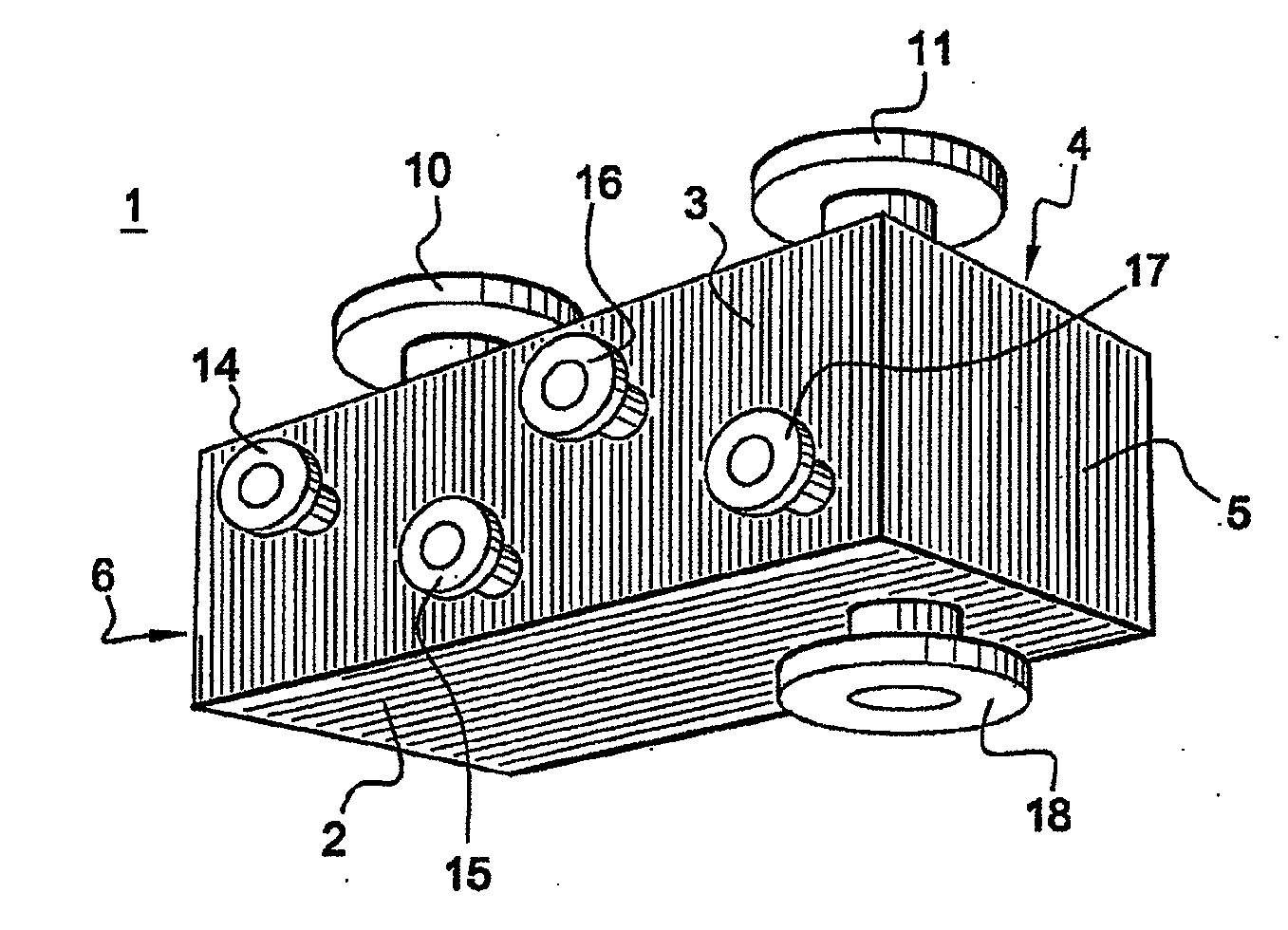
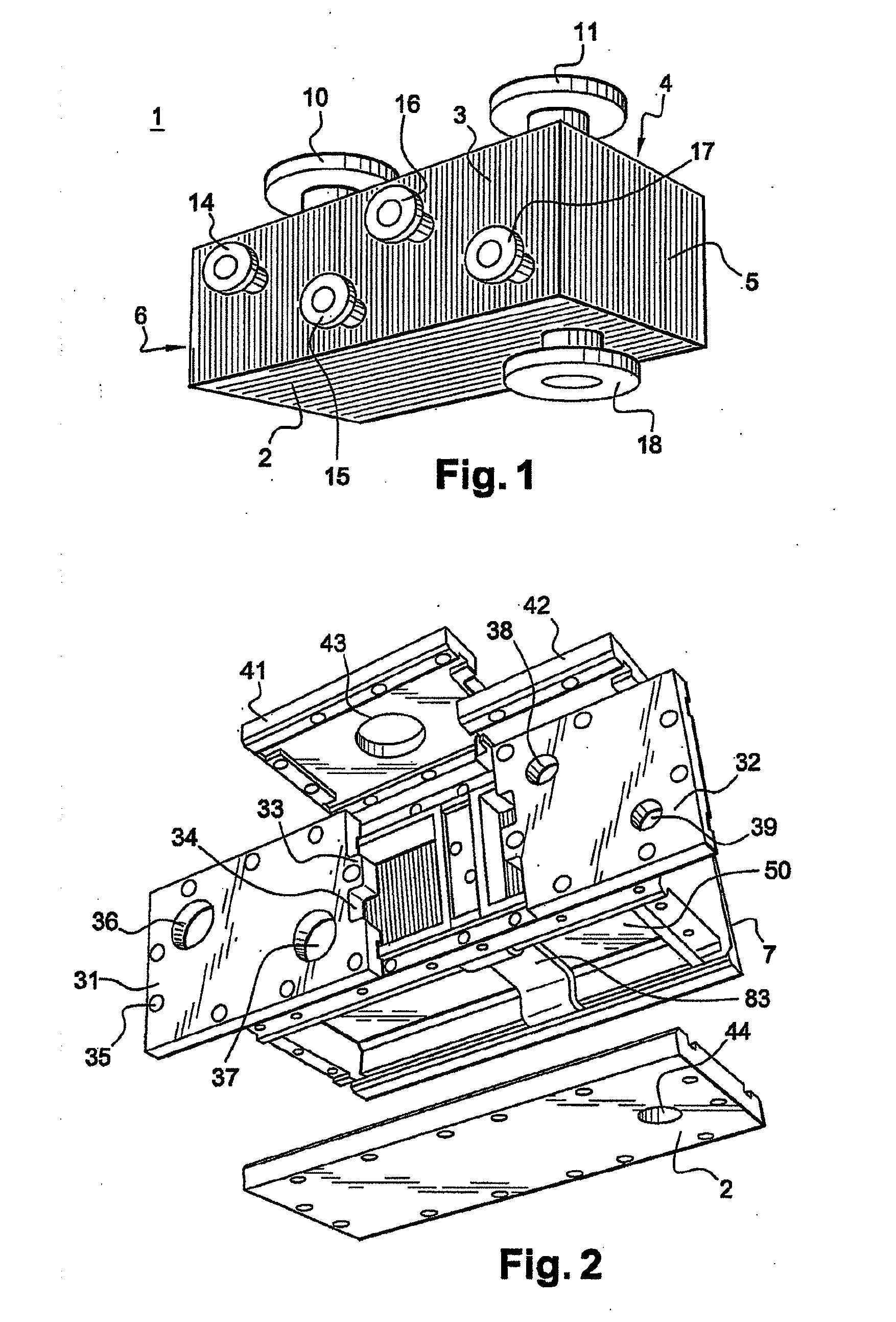
[0035]As described above, the invention relates to a heat exchanger that can be used mainly in condenser applications. Such an exchanger is shown in FIG. 1 and it is of an overall rectangular box shape defined by a set of outer walls, i.e. a lower wall (2), a frontal wall (3), an upper wall (4), a lateral wall (5, 6) and a back wall (7) seen in FIG. 2.

[0036]On upper wall (4) are disposed the inlet (10) and outlet (11) of the fluid including the matter to be condensed.

[0037]Frontal wall (3) includes the inlets of both cooling systems. More precisely, as shown in FIG. 1, frontal wall (3) comprises inlet (14) of outlet (15) on the first cooling system and inlet (16) of outlet (17) on the second cooling system. Back wall (7) enables the reflux of the coolants.

[0038]Lower wall (2) of exchanger (1) comprises outlet (18) of the condensates.

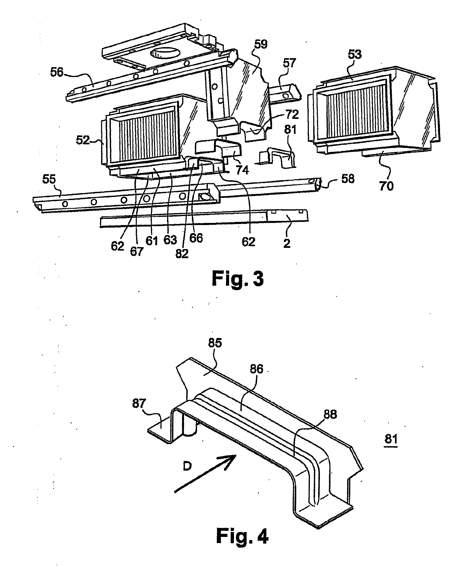
[0039]The composition of the inside of exchanger (1) is shown in greater detail in FIG. 2 wherein the various outer walls are shown separate from centre...


PUM


Abstract

A condenser-type heat exchanger having a set of welded plates that together define fluid systems that interpenetrate each other comprises at least two modules of welded plates. Each module presenting an independent cooling system (CF1, CF2), fluid (CF2) being preferably colder than fluid (CF1), and a connecting chamber that connects the two modules in series in the system of fluid to be condensed such that the direction in which the fluid to be condensed flows is reversed when it changes from one module to the next module

Description

FIELD OF THE INVENTION [0001]The invention relates to the field of heat exchangers, particularly exchangers used as condensers.[0002]It relates in particular to plate exchangers belonging to the family of welded-plate exchangers as opposed to plate exchangers produced by assembling plates together separated by peripheral seals.[0003]Welded-plate exchangers are more robust in design in that they consist exclusively of metal parts and do not include any compressible leaktight seals made of elastomer or similar materials. This design of welded-plate exchangers therefore makes them compatible with the treatment of an extremely wide range of fluids, particularly fluids that are harmful to elastomer materials. In particular the application of solvent treatments may be referred to.[0004]The invention therefore relates more specifically to a new heat exchanger structure used as a condenser.PRIOR ART [0005]Welded-plate exchangers can generally be used in applications aimed at ensuring vapour...

Claims


Application Information

Patent Timeline
IPC IPC(8): F28F9/26
CPCF28B1/02F28B2001/065F28F2265/26F28F9/26F28D9/0093
Inventor LAVANCHY, MICHELCONCOLATO, JEAN-PIERREROUSSEL, CLAUDE
Owner ALFA LAVAL VICARB
Learn More