
Plug-In Socket Provided with a Voltage Converter

a technology of voltage converter and plug-in socket, which is applied in the direction of transformer/coil connector, electrical discharge lamp, coupling device connection, etc., can solve the problems of terminal device faults, terminal device electrical specifications that cannot be satisfied by the new mains unit, etc., to achieve less expensive and reliable assembly of mains plugs, reduce production costs, and avoid complication and expenditure.

Active Publication Date: 2008-08-14
SENNHEISER ELECTRONICS GMBH & CO KG
View PDF13 Cites 3 Cited by
  • Summary
  • Abstract
  • Description
  • Claims
  • Application Information

AI Technical Summary

Benefits of technology

[0016]Integration of the voltage conversion means into the socket housing of a plug-in socket according to the invention affords numerous advantages. Firstly, the plug-in socket according to the invention prevents the user being able to replace an external mains unit with voltage converter by another mains unit with a standard mains plug which also fits—which therefore corresponds. That exchange can have the result that the electrical specifications of the terminal device are not satisfied by the new mains unit. The consequence are faults and malfunctions of the terminal device which are generally attributed to the respective terminal device by the user. If however the voltage converter is integrated in the plug-in socket of the terminal device, a simple conventional cable connection is sufficient for connecting the terminal device to the mains voltage. The electrical specification which is generally difficult to understand from the point of view of the final consumer is thus no longer of significance. That results in a lower susceptibility to faults.
[0018]Preferably the plug-in socket has a mains switch which is also integrated into the socket housing for interrupting the primary circuit, wherein the external dimensions of the socket housing are substantially predetermined by the dimensions of the corresponding standard plug and the mains switch. That measure according to the invention can provide that, in addition to the above-mentioned advantages, the terminal device can be set to a genuine zero consumption. That is successfully possible only if the primary circuit is interrupted. When the secondary circuit is switched off, there is still a residual current consumption. That counteracts the problem of parasitic or unwanted stand-by current consumption which on an annual basis causes immense costs in households. With conventional mains units which are disposed outside the terminal device in the proximity of the plug, mounting a switch is at least inconvenient or even impossible. In accordance with the present invention it is now possible to interrupt the primary circuit directly at the device and nonetheless to enjoy the advantages which, in consideration of the approval provisions and safety checks, were only afforded to the devices which have an external mains unit. In particular, that also makes it possible to meet future requirements if all electrical devices are one day to be equipped with a primary mains switch. Primary mains switches on the terminal device are virtually impossible when using plug mains units.
[0020]Preferably the socket housing of the plug-in socket according to the invention is hermetically sealed and has no additional convection. Hermetic closure and the avoidance of additional convection phenomena is a further prerequisite for shifting the safety requirements from the terminal device into the plug-in socket according to the invention, and thereby saving on costs. Equally that can facilitate installation of the plug-in socket. Preferably the plug-in socket is fixedly connected to the housing of the terminal device in manufacture of the terminal device.
[0026]It is particularly preferred if the plug-in socket can be coupled to corresponding electrical contact means of standard mains plugs in accordance with the Euro-standard. It is further preferred if the plug-in socket can be coupled to corresponding electrical contact means of standard plugs in accordance with the American standard. Those embodiments are particularly advantageous for the reason that the external contour of the housing portion of the plug, which is to be pushed in, is always substantially the same in accordance with those standards, and it is only the contact elements which are predominantly in the form of contact pins, that are at a differing spacing corresponding to the standards. That permits predictable complication and expenditure in manufacture of the plug-in socket according to the invention.
[0028]It is further preferred if the voltage conversion means are not only of a compact, closed one-piece structural configuration but also have an arrangement of the electrical contacts which, when stacking a plurality of voltage conversion means of the same structure in the socket housing of the plug-in socket, permits simple—almost automatic—electrical coupling, in particular parallel connection, of the voltage conversion means which are of the same structure, so that the required output power of the plug-in socket is adjustable in stages by electrical coupling of the plurality of voltage conversion means. In that way production procedures can be simplified and plug-in sockets which are externally of the same structure can be provided for different secondary currents. In particular the increase in the output power is facilitated by an advantageous position in respect of the contacts—that is to say the inputs and outputs—of the voltage conversion means, if they are for example all arranged on the same respective and easily accessible side of an externally one-piece voltage converter. In comparison with conventional microelectronic circuits, for example microchips, the invention affords the advantage that the contacts are provided specifically for a given stacking configuration. That is not possible to achieve with conventional integrated circuits.

Problems solved by technology

That exchange can have the result that the electrical specifications of the terminal device are not satisfied by the new mains unit.
The consequence are faults and malfunctions of the terminal device which are generally attributed to the respective terminal device by the user.

Method used


Image

  • Plug-In Socket Provided with a Voltage Converter
  • Plug-In Socket Provided with a Voltage Converter
  • Plug-In Socket Provided with a Voltage Converter

Examples


Embodiment Construction

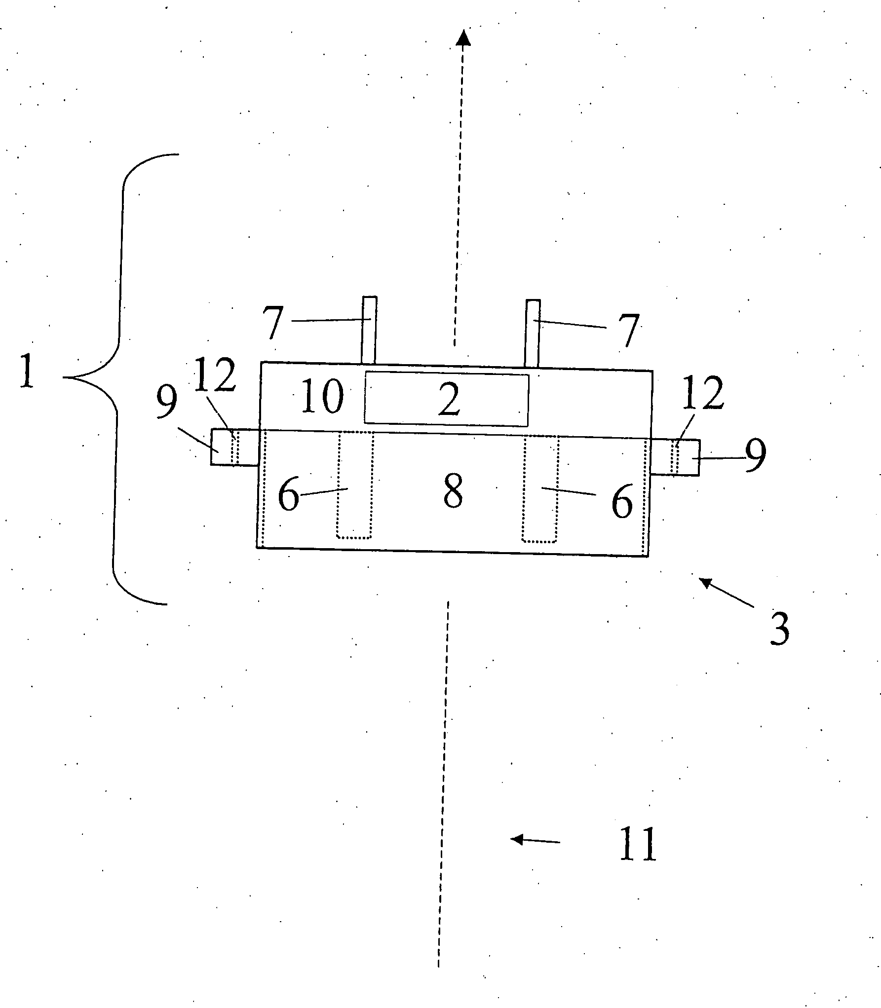
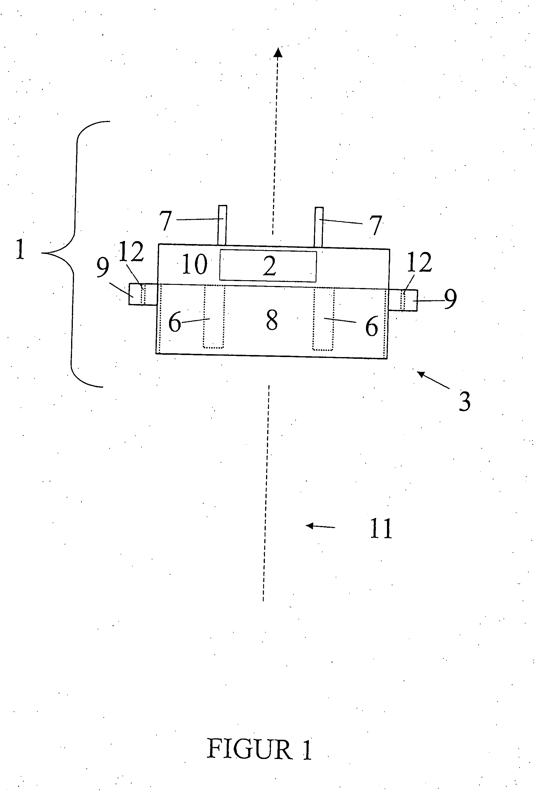
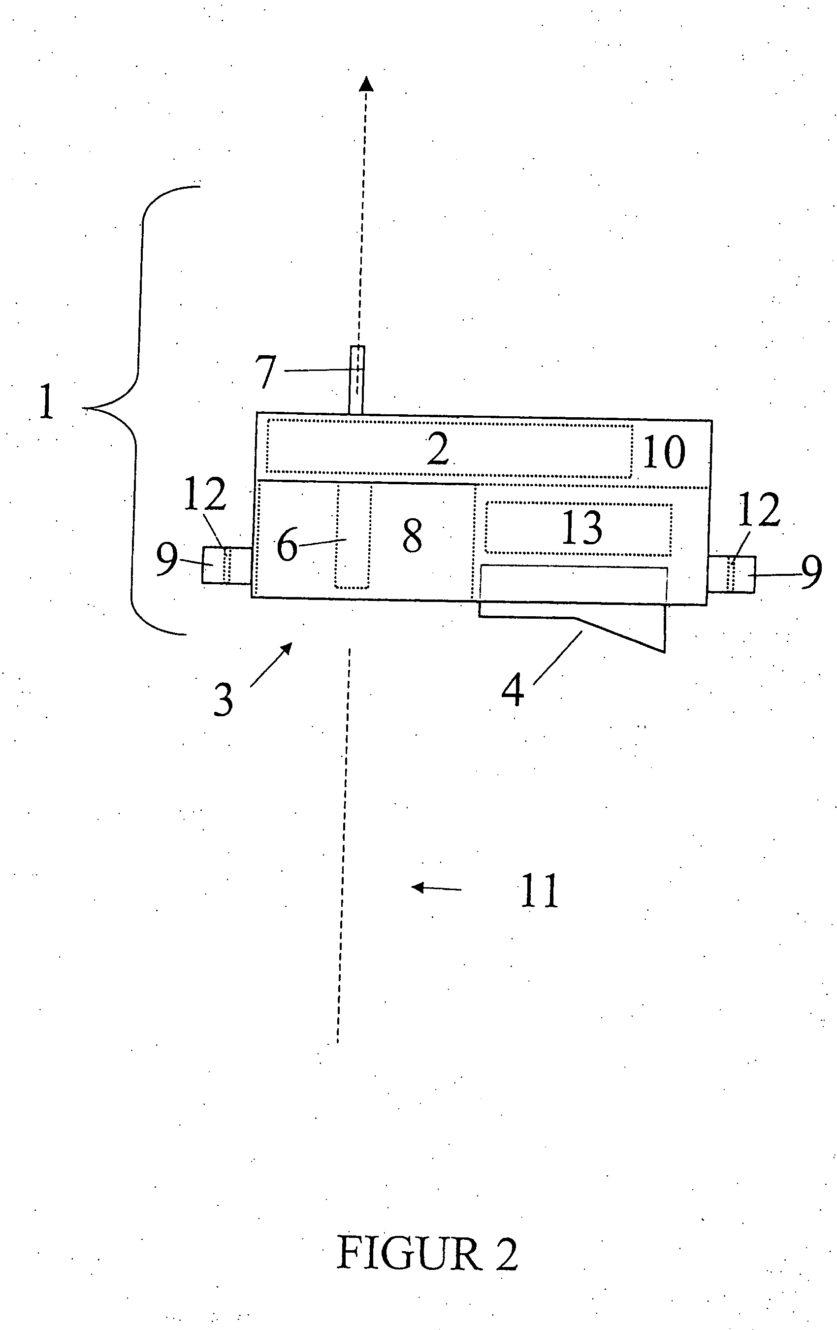
[0039]FIG. 1 shows an embodiment of a plug-in socket according to the invention. This diagrammatic lateral view in section shows the essential components of the plug-in socket 1 according to the invention. They are the socket housing 1 in which the voltage conversion means 2 are integrated. The first electrical contact means 6 for contacting with the electrical contact means of a corresponding standard plug are in this embodiment enclosed by

[0040]the socket housing 3. In that respect, provided in the push-in insertion direction 11 is a push-in opening or a push-in chamber 8 into which the corresponding standard plug can be pushed. The second electrical contact means 7 for connection of the secondary voltage within the terminal device project out of the socket housing 3 in this embodiment. However they can equally be angled, bear flat against the socket housing 3 or be integrated therein as long as they are still contactable. Typically, the voltage conversion means 2 are disposed in ...


PUM


Abstract

The invention concerns mains units for voltage conversion for electronic terminal devices. The invention concerns in particular a plug-in socket for coupling to corresponding standard plugs and for connecting an electrical terminal device to a voltage supply. The invention also concerns means for voltage conversion for a plug-in socket. The object of the invention is to improve the use of mains units with voltage conversion means, in comparison with the state of the art. The object is attained by a plug-in socket for coupling to corresponding standard plugs and for connection of an electrical terminal device to a primary voltage, comprising a socket housing, first electrical contact device arranged in the socket housing for coupling to corresponding electrical contact device of the standard plugs, a device integrated in the socket housing for voltage conversion of a primary voltage into at least one secondary voltage for the electrical terminal device, second electrical contact device arranged on the socket housing for electrical contacting of the secondary voltage and wherein the voltage conversion device are integrated in the socket housing so that the external dimensions of the socket housing are substantially predetermined by the dimensions of the corresponding standard plug. The object is further attained by voltage conversion device for a plug-in socket as set forth above comprising a closed one-part structural form. The object is still further attained by an electrical terminal device comprising a plug-in socket as set forth above.

Description

CROSS-REFERENCE TO RELATED APPLICATIONS[0001]This application claims priority of International Application No. PCT / EP2006 / 002001, filed Mar. 4, 2006 and German Application No. 10 2005 010 866.0, filed Mar. 7, 2005, the complete disclosures of which are hereby incorporated by reference.BACKGROUND OF THE INVENTION[0002]a) Field of the Invention[0003]The invention concerns mains units for voltage conversion for electronic terminal devices. The invention concerns in particular a plug-in socket for coupling to corresponding standard plugs and for connecting an electrical terminal device to a voltage supply. The invention also concerns means for voltage conversion for a plug-in socket.[0004]b) Description of the Related Art[0005]Voltage converters in the form of what are referred to as mains units have been known for some time. They convert a primary voltage (for example a mains voltage) into a secondary voltage. In a wide-spread form those mains units are disposed in a separate housing a...

Claims


Application Information

Patent Timeline
IPC IPC(8): H01R24/00H01R13/68
CPCH01R13/652H01R13/6633H01R13/68H01R13/70H01R2201/22H01R29/00H01R31/065H01R2103/00H01R24/70
Inventor GLEISSNER, ACHIMJEHLE, CHRISTOPH
Owner SENNHEISER ELECTRONICS GMBH & CO KG
Learn More