
Universal Pistol Magazine Loader

a magazine loader and universal technology, applied in the field of universal pistol magazine loaders, can solve the problems of slowing down the loading process, affecting the loading effect, and requiring bare fingers, so as to facilitate the loading of loose rounds into a magazine quickly and easily, reduce fatigue, and facilitate the effect of loading

Active Publication Date: 2008-08-07
MAGLULA
View PDF36 Cites 44 Cited by
  • Summary
  • Abstract
  • Description
  • Claims
  • Application Information

AI Technical Summary

Benefits of technology

[0059]Accordingly, several advantages of one or more aspects of the invention are to provide (a) a method and mechanism for automatically allowing a wide range of different magazines to be loaded with a single magazine loader for facilitating loading of loose rounds into a magazine quickly and easily, (b) a loader which is workable at relatively high speed with minimal fatigue to a user's fingers, and where no force will be exerted on a single finger, (c) a durable loader that is simple to operate in tough, varying, military conditions, and (d) a low-cost, pocket-size, lightweight loader comprising few parts. Further advantages of one or more aspects will become apparent from a consideration of the drawings and ensuing description.

Problems solved by technology

Loading magazines is relatively time-consuming, tedious, and painful practice if done with bare fingers.
Pain accumulates and intensifies as more rounds are loaded against the increasing spring pressure, therefore slowing the loading process.
When a plurality of magazines are to be loaded, much time is required, shortening reposing, training, or combat time.
In combat circumstances, slow reloading can be life-threatening.
US patent D477,047 to Springer, Jul. 8, 2003.Such loaders do not relieve the user from manually pushing the newly inserted round rearwardly against the spring pressure, all the way back into place below the lips.
While these are the most common loaders available in the market, they are of limited value as the fingers still accumulate pain when pushing the rounds in, and are limited in the range of magazines each can load.C.
These include:a. U.S. Pat. No. 4,304,062 to Pepe et al., Dec. 8, 1981;b. U.S. Pat. No. 6,678,985 to Pikula, Jan. 20, 2004.Such loaders are slow to use since time is spent laying the rounds into place and they require much practice to load the rounds.E.
While it may facilitate loading, the necessity of attachment, sliding a new round in, and detachment makes its use inefficient, tedious, and awkward.
It further lacks a structure which is comfortable for repeated use against the magazine's spring pressure, and is generally flimsy and delicate to use under field conditions.
Further, it is not efficient to load magazines having rounded front walls as it has a flat base which causes a tray to be misaligned with the topmost round, causing the tray to usually engage a lip of the magazine.
This pressure on the thumb makes this loader painful and uncomfortable for repeated use.
Although it pushes a topmost round using a hinged lever, it does not allow sufficient vacant space immediately above that round as the pressing plunger blocks the space required for loading a pistol magazine (but not a rifle magazine).
Once more, a plunger pushes a topmost round using a hinged lever not allowing sufficient vacant space immediately above that round as the plunger blocks the space required for loading a pistol magazine.
This loader is uncomfortable and relatively slow to use, and comprise relatively many parts.
In summary, bare finger pistol magazine loading is tedious, cumbersome, and injurious.
While several accessories have been provided for facilitating this chore, none are able to load loose rounds into a magazine efficiently, rapidly, safely, easily, and painlessly.
Further, while there have been attempts to provide a mechanism for accepting large range of different pistol magazines in a single magazine loader, none was able to do just that, and all are quite limited in the range of magazine they accept.
Further, all existing ‘adjustable’ loaders have to be adjusted prior to use, and none has an automatic adjusting means.

Method used


Image

  • Universal Pistol Magazine Loader
  • Universal Pistol Magazine Loader
  • Universal Pistol Magazine Loader

Examples


embodiment

Preferred Embodiment

FIGS. 1A-1F—Simplified Diagrams

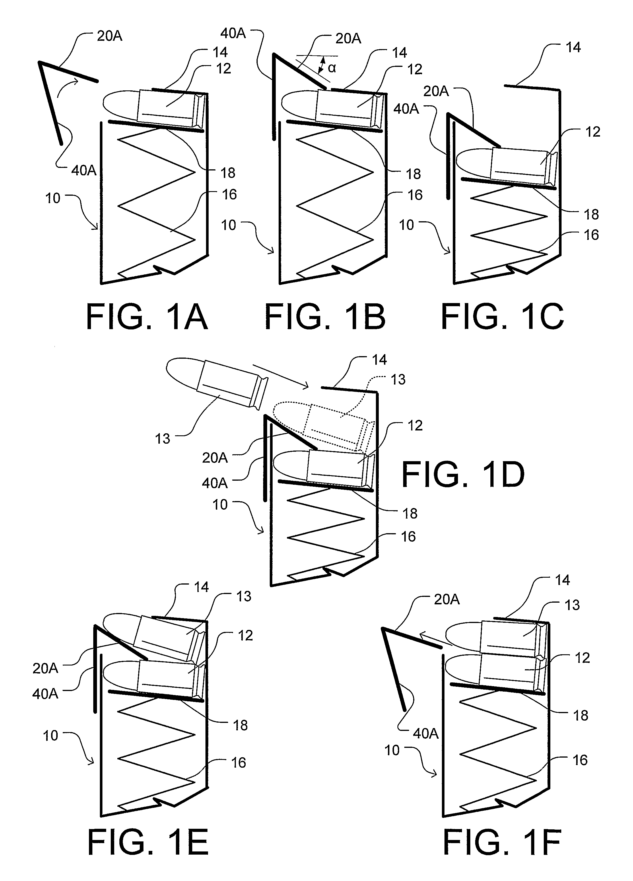
[0099]FIG. 1A to 1F are simplified side sectional schematic diagrams illustrating the hardware and loading method according to the invention.

[0100]FIG. 1A shows a magazine 10 loaded with a topmost round 12 retained by a lip 14 of the magazine and pushed up against the lip by a follower 18 which is in turn urged up by a spring 16 of the magazine. A simplified plunger or pusher 20A is also shown at a first ‘away’ position in front or to the left and relatively distant from the open side of magazine 10 and round 12. The plunger is rigid and thin having a free end or edge, shown connected to a simplified press 40A.

[0101]FIG. 1B shows a second or ‘close’ position of the plunger, moved over the magazine and partially above topmost round 12 with its right (front) edge over the left side of the case. The plunger has a downward angle α with the horizontal.

[0102]FIG. 1C shows the plunger down in the magazine pressing or forcing the topmost ro...


PUM


Abstract

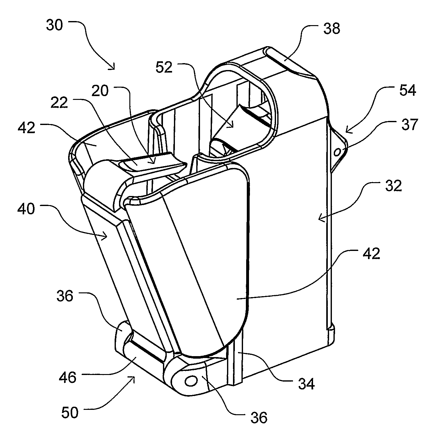
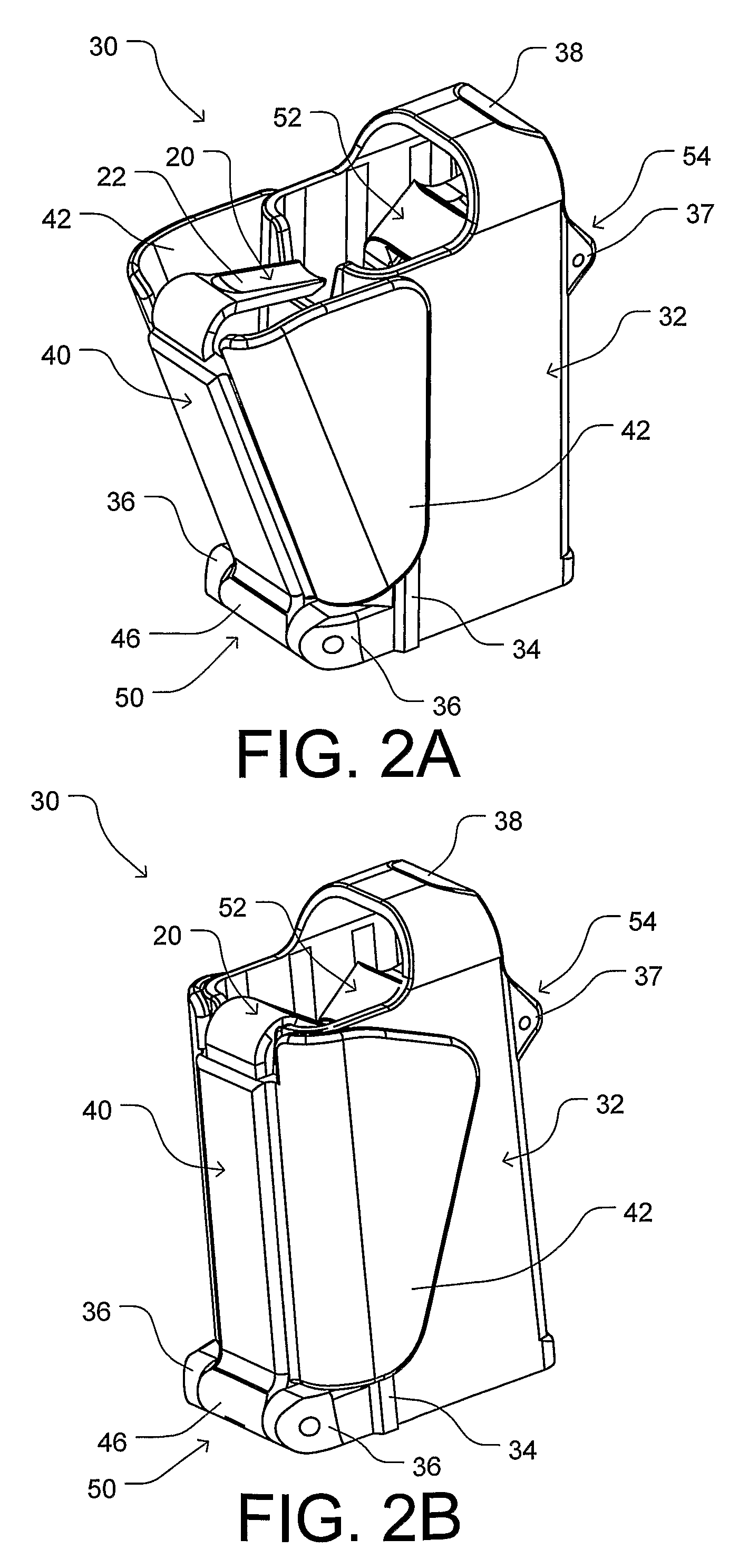
A firearm magazine loader (30) comprises a body (32) coupled to a movable press (40), a plunger (20) extending out of the press towards the body, and a magazine aligner (52). The body is hollow and adapted to fit and slide over an open side of a magazine (10). A spring (48) is positioned between the body and the press to force them apart. To load the magazine, the user squeezes the press towards the body such that plunger is over a topmost round (12) in the magazine, and then presses down the loader, causing the plunger to force the topmost round further into the magazine to form a vacant space below lips (14) of the magazine. This enables a new round (13) to be rearwardly, case first, loaded inside the vacant space. The user then eases the down force on the loader allowing the spring (16) of the magazine to force up all the rounds in the magazine towards the lips while releasing the press for allowing the spring of the press to force the press and plunger back to their original position. The magazine aligner is positioned inside the body for centering the open side of magazines of different widths and depth mounted in the loader in line with the plunger.

Description

CROSS-REFERENCE TO RELATED APPLICATIONS[0001]This application claims the benefit of U.S. Provisional Patent Application Ser. No. 60 / 671,400 filed Apr. 15, 2005, and U.S. Provisional Patent Application Ser. No. 60 / 736,005, filed Nov. 14, 2005.BACKGROUND[0002]1. Field of Invention[0003]The invention relates to firearms, particularly to a method and accessory for facilitating loading of firearm rounds into a firearm magazine.[0004]2. Prior Art[0005]Many small firearms, including pistols, assault rifles, and submachine guns, utilize and fire rounds (also known as cartridges and ammunition). Each round is substantially elongated and comprises a deep cuplike case (also known as a shell casing and sometimes also a cartridge), usually of brass, which is filled with an explosive propellant. At its rear or closed end, the case has a rim or flange containing a primer; the front and opposite end of the case is open. A bullet, slug, or head, usually of lead (optionally jacketed) is partially ins...

Claims


Application Information

Patent Timeline
Patent Type & Authority Applications(United States)
IPC IPC(8): F41A9/83
CPCF41A9/83
Inventor TAL, GUYTAL, RAN
Owner MAGLULA
Learn More