
Optical disc case, optical disc tray, card member, and manufacturing method

a technology of optical discs and optical discs, applied in the direction of data recording, instruments, sensing record carriers, etc., can solve the problems of time-consuming, complex action, and difficulty in communication with non-contact ic chips

Inactive Publication Date: 2008-07-31
SONY CORP
View PDF4 Cites 76 Cited by
  • Summary
  • Abstract
  • Description
  • Claims
  • Application Information

AI Technical Summary

Benefits of technology

[0015]There has been recognized a need for an optical disc case whereby communication with the non-contact IC chip on an optical disc can be readily performed even in a case wherein a reader / writer is approached from the case side face perpendicular to the recording face of the optical disc, and also there is no great difference from the basic configuration of an existing optical disc, an optical disc tray and card member for this optical disc case, and methods for manufacturing this optical disc case and optical disc tray.
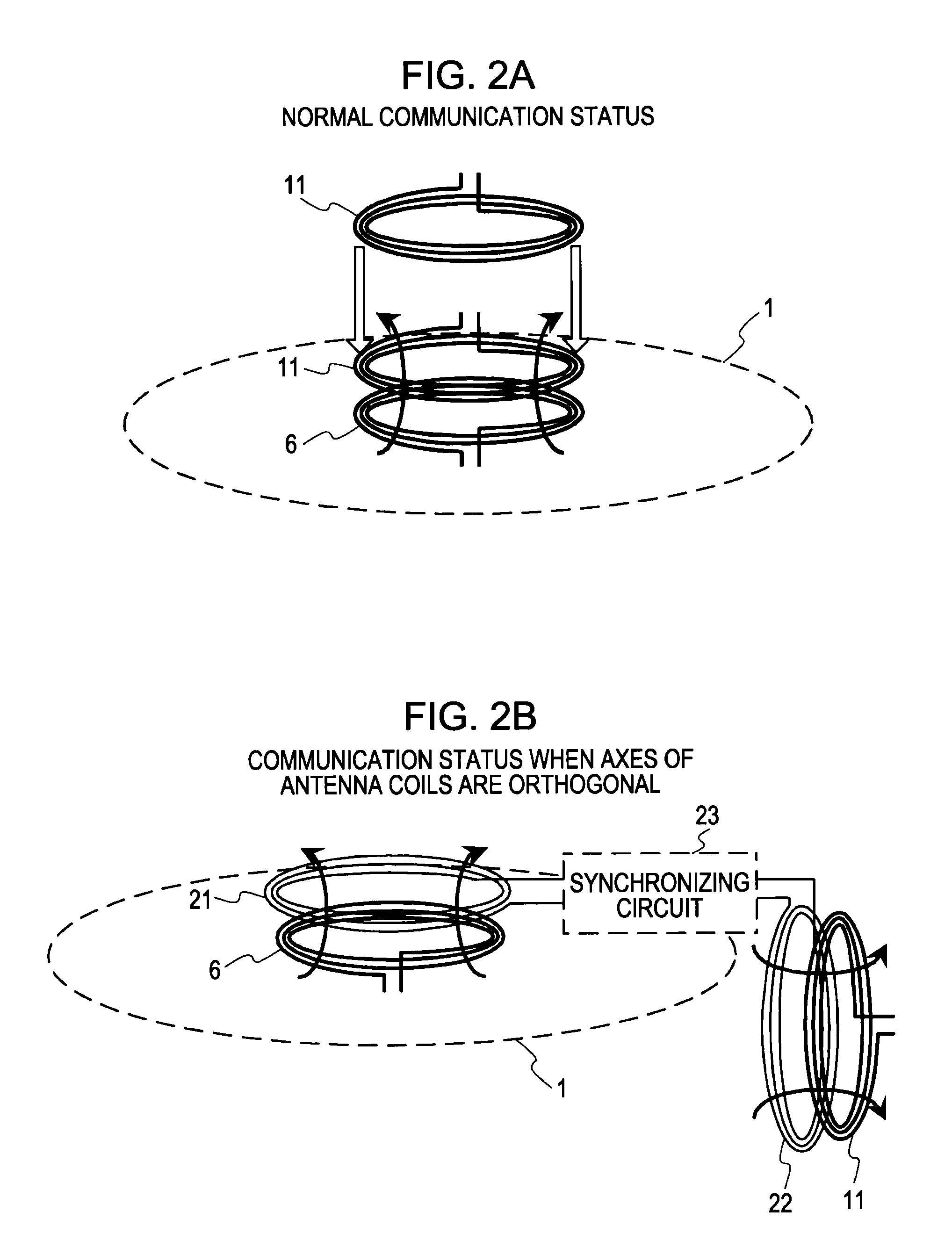
[0038]Also, with the optical disc tray according to an embodiment of the present invention, this optical disc tray is disposed within the case casing of the optical disc case configured of the face cover portion and the rear-face cover portion which are connected so as to be rotated with the end portion side of each principal face as the center by the optical disc tray being fitted into and attached to the rear-face cover portion so as to direct the holding face of an optical disc to the inner side of the case casing, and also an optical disc where a non-contact IC chip, and a non-contact communication antenna formed with the rotation center of the optical disc as the center are provided is held by the protruding holding portion, and in a state in which the optical disc case thereof is closed, the reader / writer of the IC chip comes close to the case side face corresponding to the position of the second antenna, whereby communication can be performed between the reader / writer and the IC chip on the optical disc in a sure manner. Also, there is no need to change the basic configuration of an optical disc case which has already come into widespread use, and the booster antenna is disposed in an optical disc tray making up the optical disc case thereof, whereby the above-mentioned advantages can be obtained.
[0039]Further, with the card member according to an embodiment of the present invention, this card member is disposed so as to cover the outer faces of the face cover portion, rear-face cover portion, and side-face portion of the optical disc case, and also an optical disc where a non-contact IC chip, and a non-contact communication antenna formed with the rotation center of the optical disc as the center are provided is held within the rear-face cover portion of the optical disc case thereof, and in a state in which the optical disc case thereof is closed, the reader / writer of the IC chip comes close to the side face portion of the optical disc case, whereby communication can be performed between the reader / writer and the IC chip on the optical disc in a sure manner. Also, there is no need at all to change the configuration of the optical disc case which has already come into widespread use, and rather the card member is simply disposed so as to cover the outer face of the optical disc case thereof, whereby the above-mentioned advantages can be obtained.
[0040]Also, with the card member according to an embodiment of the present invention, this card member is accommodated between the disc tray member and the rear-face cover portion, and also an optical disc where a non-contact IC chip, and a non-contact communication antenna formed with the rotation center of the optical disc as the center are provided is held within the rear-face cover portion of the optical disc case thereof, and in a state in which the optical disc case thereof is closed, the reader / writer of the IC chip comes close to the side face portion of the optical disc case, whereby communication can be performed between the reader / writer and the IC chip on the optical disc in a sure manner. Also, there is no need at all to change the configuration of an optical disc case which has already come into widespread use, and rather the card member is simply disposed between the disc tray member and the rear-face cover portion, whereby the above-mentioned advantages can be obtained.
[0042]Also, with the card member according to an embodiment of the present invention, this card member is disposed so as to cover the outer faces of the face cover portion, rear-face cover portion, and side-face portion of the optical disc case, and also multiple optical discs each on which a non-contact IC chip, and a non-contact communication antenna formed around the disc rotation center are provided are held within the optical disc case thereof, and in a state in which the optical disc case thereof is closed, the reader / writer of the IC chip comes close to the side face portion of the optical disc case, whereby communication can be performed between the reader / writer and the IC chip on each optical disc in a sure manner. Also, there is no need at all to change the configuration of an optical disc case which has already come into widespread use, and rather the card member is simply disposed so as to cover the outer face of the optical disc case thereof, whereby the above-mentioned advantages can be obtained.

Problems solved by technology

Note however, in such a situation, the optical discs on the storage rack are in a state in which the recording faces thereof are approached to face each other, so the antenna surface of a reader / writer cannot be approached in parallel to the recording faces thereof, which makes it difficult to perform communication with the non-contact IC chips.
Therefore, when attempting to consecutively communicate with the non-contact IC chips of the multiple optical discs within a storage case in order, such a complex action needs to be performed, which requires time.
Note however, this arrangement needs to provide a dedicated storage rack integral with a reading device, so neither a storage rack which the user has already used nor a general-purpose reading device which can be carried can be used.

Method used


Image

  • Optical disc case, optical disc tray, card member, and manufacturing method
  • Optical disc case, optical disc tray, card member, and manufacturing method
  • Optical disc case, optical disc tray, card member, and manufacturing method

Examples


embodiment 1-1

[0127]FIG. 4 is a diagram illustrating the outer shape of an optical disc case according to Embodiment 1-1. In FIG. 4, an optical disc case 30 is a container case made of a resin where the optical disc 1 is attached to the inside thereof, and the outer shape thereof forms a rectangular solid of which the direction perpendicular to the disc face is thinner. Also, with the side face to be connected to one side of the face (case principal face) parallel to the disc face, an antenna coil 22 making up the booster antenna 20 for transmitting / receiving a signal to / from the external reader / writer 10 is provided close thereto. With the example shown in FIG. 4, the side face at the connection portion side where the cover portion is connected to the base portion of the optical disc case 30 rotatably is provided with the antenna coil 22 for performing communication with the reader / writer 10. Also, the other antenna coil 21 (not shown) making up the booster antenna 20 is provided within the opti...

embodiment 1-2

[0155]FIG. 8 is an exploded perspective view of an optical disc case according to Embodiment 1-2. The optical case 30a shown in FIG. 8 is a modification of the optical disc case 30 according to Embodiment 1-1, wherein the booster antenna unit 20b is disposed not on the disc-mounted face 35 of the disc tray 33 but on the rear face thereof. With the booster antenna unit 20b to be implemented in the optical disc case 30, the antenna coil 22 for communication with the reader / writer 10 is bent upward with the bending portion 27a between the antenna coil 22 and connection wiring 24 as a boundary, and is in a state perpendicular to the case principal face.

[0156]In the event of manufacturing such an optical disc case 30a, for example, following the booster antenna unit 20b being subjected to bending work at the bending portion 27a, the booster antenna unit 20b is fastened to the opposite face of the disc-mounted face 35 of the disc tray 33. Subsequently, the disc tray 33 to which the booste...

embodiment 2

[0158]FIG. 9 is a perspective view illustrating the configuration of an optical disc case according to Embodiment 2. The optical disc case 40 shown in this FIG. 9 is configured of a base portion 41 and a cover portion 42, and the base portion 41 and cover portion 43 are connected at a connection portion 43 so as to be rotated. Also, unlike Embodiments 1-1 and 1-2, an arrangement is made wherein a disc-mounted face 44 and a disc holding portion 45 are formed integral with the inner face of the base portion 41, and the optical disc 1 is accommodated at the inner side of the base portion 41. The base portion 41 and cover portion 42 are formed of a polystyrene resin material. The optical disc case 40 having such a basic configuration is an optical disc case which has been widely circulated as a container case for CDs, DVDs, and so forth, which is thinner than the optical disc cases having the configurations shown in Embodiments 1-1 and 1-2.

[0159]Subsequently, with the present embodiment...


PUM


Abstract

An optical disc case, in which an optical disc is stored, wherein a face cover portion and a rear-face cover portion are connected so as to be rotated with the end portion side of each of the principal faces thereof as the center, and are configured so as to form a box-shaped appearance when the face cover portion and the rear-face cover portion are closed such that the respective principal faces of the face cover portion and the rear-face cover portion face each other, the case including: a protruding holding portion, configured to fit into a central hole formed in the optical disc to hold the optical disc, provided to the inner side of the principal face of the rear-face cover portion; and a booster antenna to which a first antenna and a second antenna are connected configured to relay a signal sent / received from one antenna to the other antenna.

Description

CROSS REFERENCES TO RELATED APPLICATIONS[0001]The present invention contains subject matter related to Japanese Patent Application JP 2007-018682 filed in the Japanese Patent Office on Jan. 30, 2007, Japanese Patent Application JP 2007-056741 filed in the Japanese Patent Office on Mar. 7, 2007, Japanese Patent Application JP 2007-212424 filed in the Japanese Patent Office on Aug. 16, 2007, and Japanese Patent Application JP 2007-212425 filed in the Japanese Patent Office on Aug. 16, 2007, the entire contents of which are incorporated herein by reference.BACKGROUND OF THE INVENTION[0002]1. Field of the Invention[0003]The present invention relates to an optical disc case in which an optical disc is stored, a disc tray and a card member to be attached to this case, and a method for manufacturing the optical disc and optical disc tray, and particularly, relates to an optical disc case, a disc tray and a card member, which are suitable for storing an optical disc on which a non-contact I...

Claims


Application Information

Patent Timeline
IPC IPC(8): G11B33/02
CPCG06K7/10178G06K19/07749G06K19/045
Inventor ASHIZAKI, KOJITOYODA, TAKAHIROORIHARA, KATSUHISA
Owner SONY CORP
Learn More