
Method and apparatus for torque control for machinery using counter-rotating drives

a technology of torque control and counter-rotating drive, applied in the direction of instruments, special-purpose vessels, vessel movement reduction by jet/propeller, etc., can solve the problems of drag on the control surface of the roll, vehicle to exhibit one or more unwanted angular movements, and special-purpose vessel drag, etc., to reduce the error

Inactive Publication Date: 2008-07-31
VIRGINIA TECH INTPROP INC
View PDF23 Cites 21 Cited by
  • Summary
  • Abstract
  • Description
  • Claims
  • Application Information

AI Technical Summary

Benefits of technology

The patent describes a way to make vehicles that can be controlled and stabilized in real-time, even when they are moving through a medium like water. This is possible because the system uses feedback to automatically adjust the amount of force applied to the vehicle by rotating parts that are attached to it. This technology can be used to create vehicles that can be controlled and operated in ways that would be difficult or impossible without this system.

Problems solved by technology

When a water vehicle is propelled through water, hydrodynamic and other forces may cause the vehicle to exhibit one or more unwanted angular movements, generally characterized as roll, pitch and yaw.
Roll R may be particularly problematic with underwater water vehicles, because the roll inertia and the roll resistance of such vehicles are substantially lower than their inertia and resistance to pitch and yaw.
However, roll control surfaces present drag and, because roll is typically easily induced, often require robust control methods.
Further, hydrodynamic forces may result from roll control fins such that, even if proper to stabilize or correct the roll, often induce a pitch and / or yaw motion, which must then be counteracted.
Passive roll stabilization, though, has limitations.
One limitation is that requiring the center of weight to be below the center of buoyancy necessarily imposes constraints in the location of mass within the vehicle.
Another is that, due to physical constraints of mass distribution, the maximum attainable stabilizing effect is limited.
Another limitation is that the restorative force is inherently proportional to the roll, approaching zero at zero roll.
As a result, roll oscillation about the zero roll may occur.

Method used


Image

  • Method and apparatus for torque control for machinery using counter-rotating drives
  • Method and apparatus for torque control for machinery using counter-rotating drives
  • Method and apparatus for torque control for machinery using counter-rotating drives

Examples


examples applying embodiments

[0042

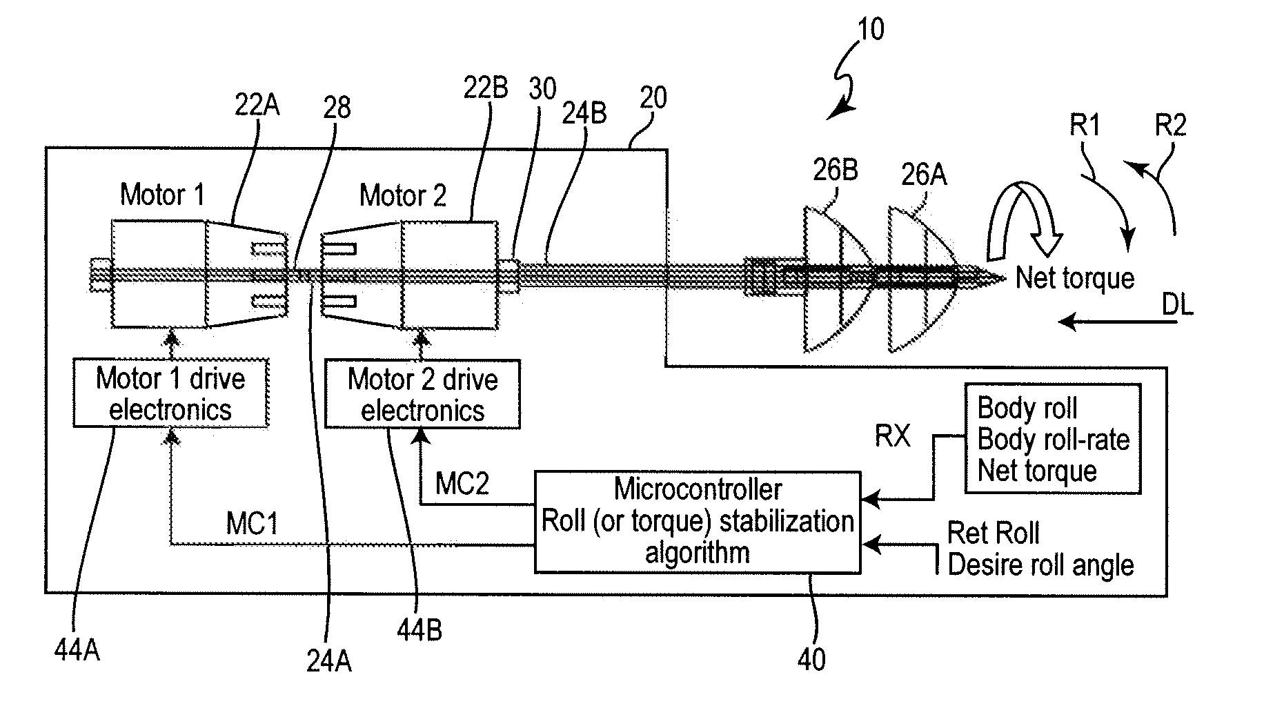
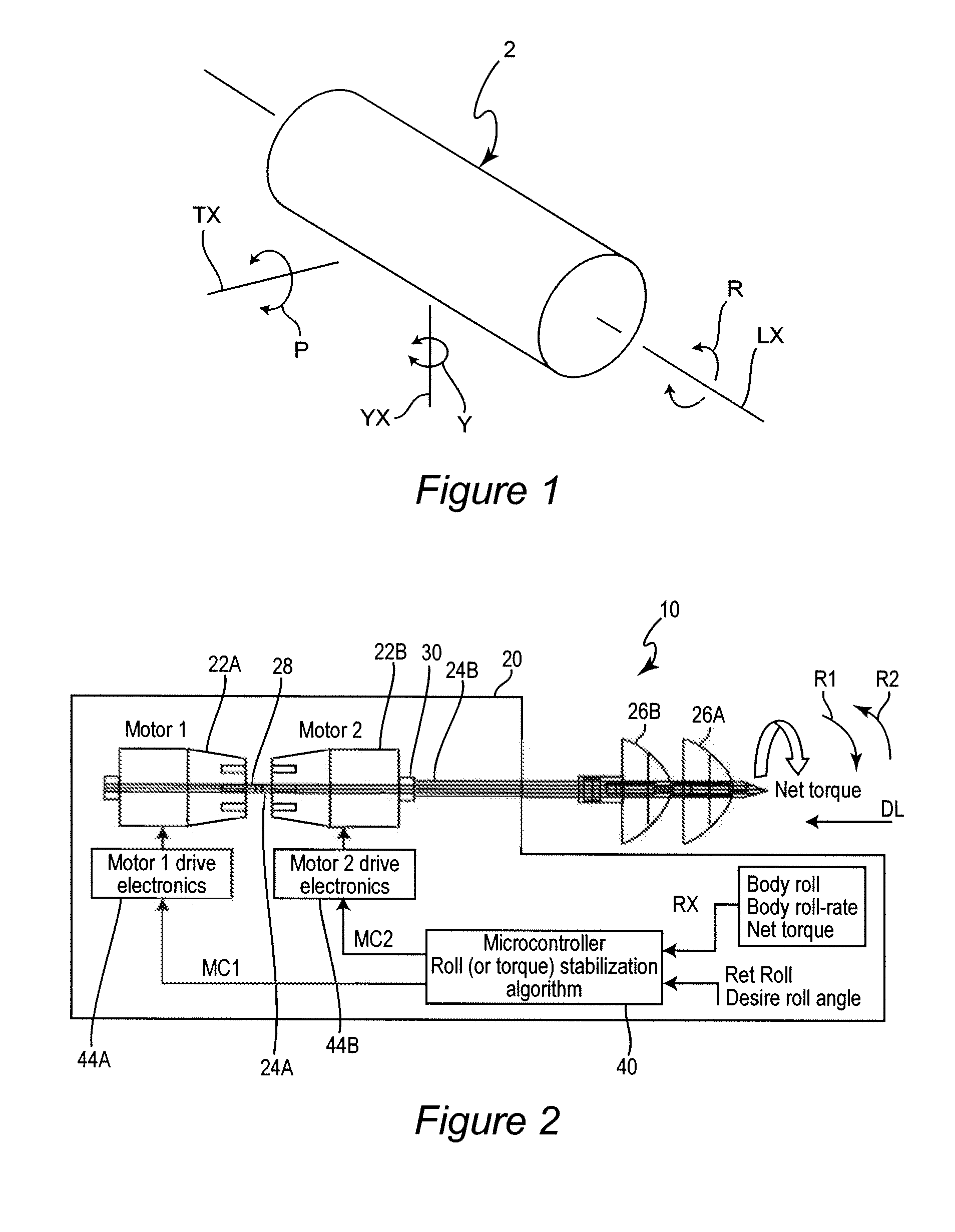
[0043]FIG. 2 represents, in schematic form, an example feedback torque control roll stabilization system 10 relating to a water vehicle 20. The water vehicle 20 may be an underwater vehicle, may be capable of surface operation, and may have conventional ballast structures and methods (not shown). Example operations are described in reference to a “vehicle roll axis RL” of vehicle 20, which may be the roll axis LX shown in FIG. 1.

[0044]Referring to the FIG. 2 example, the water vehicle 20 may include a first motor 22A and a second motor 22B. The first motor 22A and second motor 22B may be conventional electric motors for underwater vehicles, connected to conventional batteries (not shown). First motor 22A may connect or couple to a first driveshaft 24A connected or coupled to a first propeller 26A. Second motor 22B may connect or couple to a second driveshaft 24B connected or coupled to a second propeller 26B. The first motor 22A and second motor 22B are examples. An embodiment ...


PUM


Abstract

An active feedback roll stabilization and torque control for a vehicle or equipment, having a propulsion unit with counter-rotating rotary members, detects a vehicle roll or torque, detects an error between the detected roll or torque and a reference roll or torque and, based on the detected error, dynamically and individually controls the respective torque and, hence, reaction torque exerted by the counter-rotating rotary members, to obtain a net reaction torque continually urging the vehicle's roll or torque to move the error toward zero.

Description

CROSS-REFERENCE TO RELATED APPLICATIONS[0001]This application claims priority to U.S. Provisional Application Ser. No. 60 / 839,138 filed Aug. 22, 2006, which is hereby incorporated by reference in its entirety.FIELD OF THE INVENTION[0002]The embodiments relate generally to torque control and more particularly to stabilization by torque control using counter-rotating drives.BACKGROUND OF THE INVENTION[0003]When a water vehicle is propelled through water, hydrodynamic and other forces may cause the vehicle to exhibit one or more unwanted angular movements, generally characterized as roll, pitch and yaw. An example illustration is given at FIG. 1, with block 2 representing any water vehicle. Roll R is angular motion about the longitudinal axis LX of the water vehicle 2, typically extending from front to rear. Pitch P is angular motion about the water vehicle's transverse axis TX, and yaw Y is angular motion about the yaw axis YX, i.e., the axis orthogonal to both the longitudinal axis L...

Claims


Application Information

Patent Timeline
Patent Type & Authority Applications(United States)
IPC IPC(8): G05D1/08
CPCG05D1/0875B63B39/08B63G8/16
Inventor NEU, WAYNE L.HENNAGE, JOHN B.STILWELL, DANIEL J.WILLIAMS, RYAN K.PETRICH, JAN
Owner VIRGINIA TECH INTPROP INC
Learn More