Deep Shadow Occulter

a shadow occulter and deep shadow technology, applied in the field of deep shadow occulter, can solve the problems of very old diffraction problem in small angle shadows, difficult to see faint objects, and difficulty in detecting faint objects, etc., and achieve the effect of suppressing diffraction

Active Publication Date: 2008-07-31
UNIV OF COLORADO FOUND
View PDF1 Cites 10 Cited by
  • Summary
  • Abstract
  • Description
  • Claims
  • Application Information

AI Technical Summary

Benefits of technology

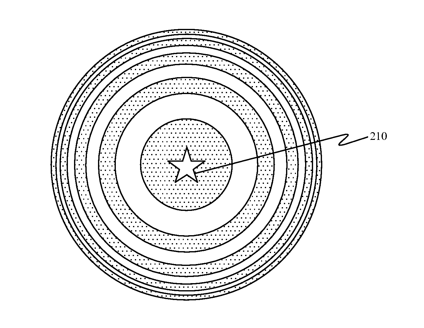
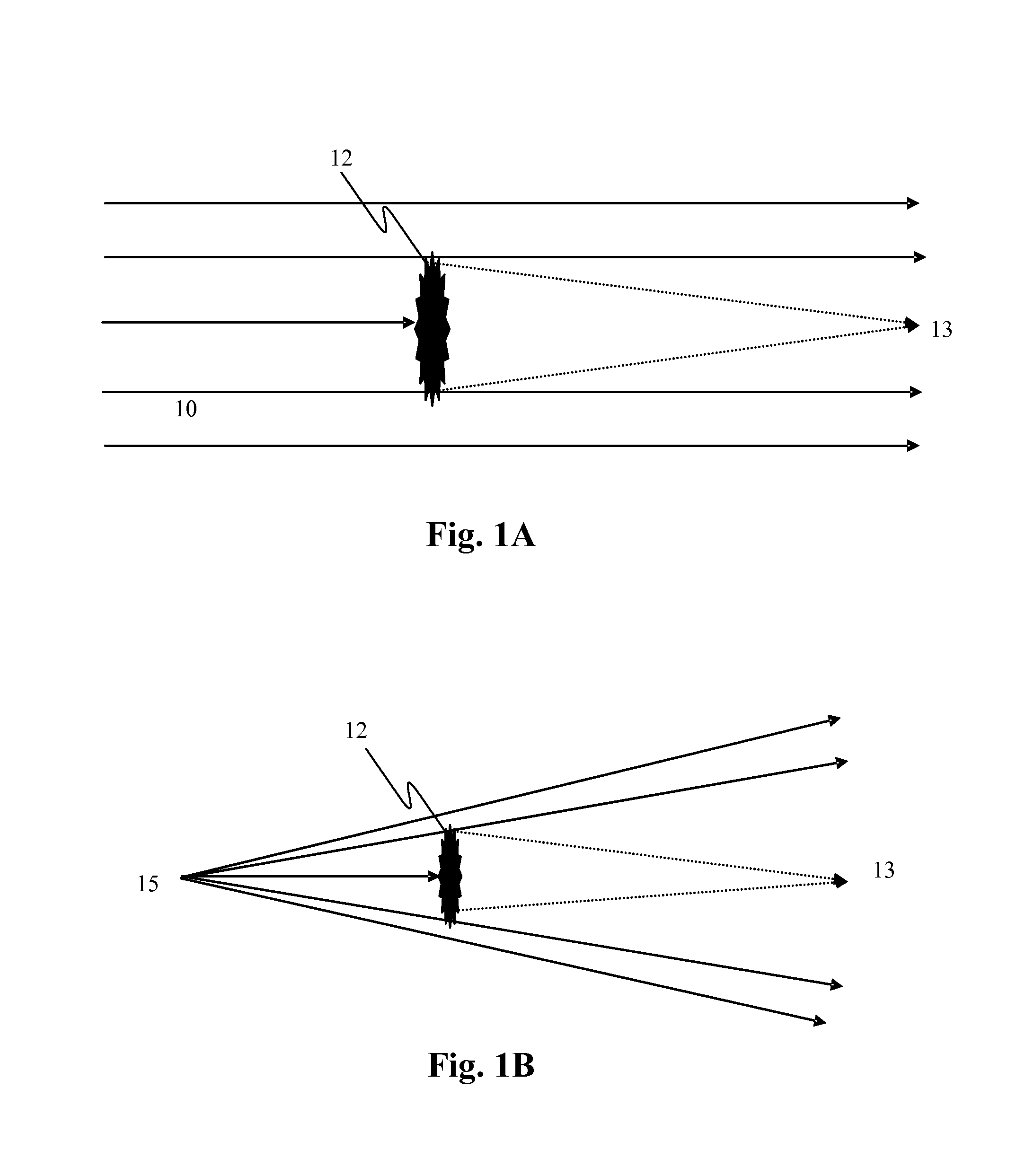
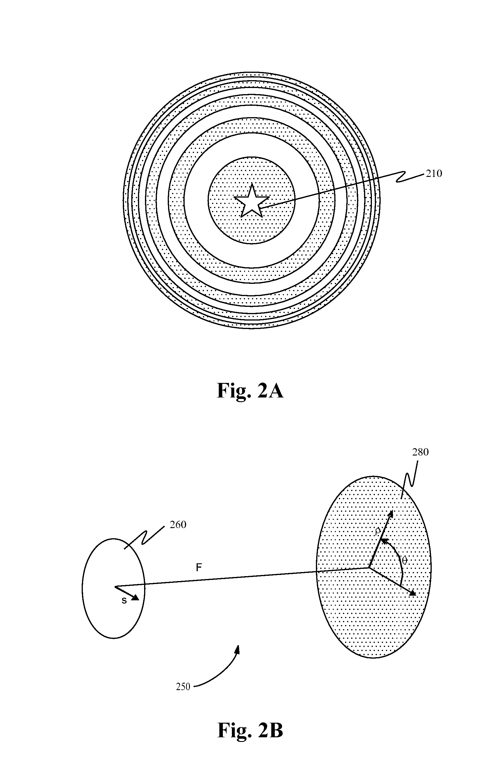
[0013]Embodiments of the invention provide methods and apparatus for occulting light. The occulter shape suppresses diffraction at any given size or angle and is practical to build because it can be made binary to avoid scatter. Binary structures may be only fully opaque or fully transmitting at any point. The diffraction suppression is spectrally broad so that it may used with incoherent white light. Embodiments of the invention find a number of different applications. For instance, on the ground, an occulter made in accordance with an embodiment may be used to create a deep shadow in a short distance. In space, an occulter made in accordance with an embodiment may be used to suppress starlight and reveal exoplanets.

Problems solved by technology

As the angular separation becomes smaller and the ratio of brightness becomes larger, seeing the faint object gets rapidly more difficult.
The problem of diffraction in small angle shadows is very old.
But often the light diffracting around the edge of an occulter lowers contrast and ruins the performance of the system.
Studies are showing that cost is very high and it will be difficult to achieve low scatter over a broad spectral band.
However, the scatter caused by the transmitting shade creates a practical limit near 10−5 anyway.

Method used


Image

  • Deep Shadow Occulter
  • Deep Shadow Occulter
  • Deep Shadow Occulter

Examples


example 1

[0074]Starshade. According to one embodiment of the invention, an occulter may be used within a telescope used to find water planets around stars. Accordingly, in one example, a starshade may be used with parameters n=6, a=b=12.5 m, and F=50,000 km. With twelve petals we find the performance shown in FIG. 4A. The brightness of a star on-axis is suppressed a factor of 1013 at 0.6μ wavelength. At 1.8μ the suppression factor has fallen to 106 as fewer Fresnel zones are covered. The transmission of the occulter rises to nearly 100% in just 25 m, which demonstrates that an object 0.1 arcseconds off-axis would be visible in the shadow. FIG. 4B shows the contrast as a function of radius and angle off-axis for this starshade. Three values of n are shown for n=8, n=12, and n=4. The shadow drops from full transmission to below 10-12 in under 30 m at visible light wavelengths. Across the top is shown the equivalent angle, demonstrating that 10-10 suppression is achievable in about a tenth of a...

example 2

[0076]Laboratory Shade. According to another embodiment of the invention a starshade may be used with n=6, and a=b=8 mm with 42 petals. Testing this starshade, a beam of solar radiation 30 m from a pinhole and 10 m from an shadow plane. Light at the center of the shadow was detected and found to be below 10−7 of the direct beam. What little signal was left was most likely scattering in the air or off the walls of the dark tunnel.

[0077]FIG. 7A shows an artist's conception of a solar system. FIG. 7B shows a simulation of an image captured of the image in FIG. 7A from 10 pc away using a large telescope with an occulter according to embodiments of the invention. The basic features of the planetary system are visible. The brightness of the star may be masked using the occulter allowing imaging of the planets within the solar system.

[0078]FIG. 8 shows an occulter 800 according to embodiments of the invention. This occulter produced 10−7 suppressions in air. The occulter includes a solid b...


PUM


Abstract

Methods and apparatus are disclosed for occulting light. The occulter shape suppresses diffraction at any given size or angle and is practical to build because it can be made binary to avoid scatter. Binary structures may be fully opaque or fully transmitting at specific points. The diffraction suppression is spectrally broad so that it may be used with incoherent white light. An occulter may also include substantially opaque inner portion and an at least partially transparent outer portion. Such occulters may be used on the ground to create a deep shadow in a short distance, or may be used in space to suppress starlight and reveal exoplanets.

Description

CROSS-REFERENCES TO RELATED APPLICATIONS[0001]This application is a non-provisional, and claims the benefit, of commonly assigned U.S. Provisional Application No. 60 / 832,535, filed Jul. 20, 2006, entitled “Deep Shadow Occulter,” the entirety of which is herein incorporated by reference for all purposes.STATEMENT AS TO RIGHTS TO INVENTIONS MADE UNDER FEDERALLY SPONSORED RESEARCH OR DEVELOPMENT[0002]The U.S. government may have rights in this invention under NASA Grant No. NAS5-03110.BACKGROUND OF THE INVENTION[0003]This application relates generally to the fields of diffraction control, high contrast imaging, and coronagraphy. More specifically, this application discloses an occulter for creation of very deep shadows across optimally small angles.[0004]Sometimes faint objects of interest appear close to much brighter sources of less interest. All optics contain some level of scattering and diffraction that can swamp the faint signal with stray light from the bright source. As the ang...

Claims


Application Information

Patent Timeline
Patent Type & Authority Applications(United States)
IPC IPC(8): G02B27/00
CPCG02B27/58
Inventor CASH, WEBSTER
Owner UNIV OF COLORADO FOUND
Why Eureka
Try Eureka