
Circuit for controlled commutation of multiplexed electrodes for an active implantable medical device

a medical device and multiplex electrode technology, applied in the field of active medical devices, can solve the problems of difficult to access the left ventricle, difficult to find, and difficult implanting procedure, so as to minimize the risk of inducing a fibrillation, avoid excessive voltage application, and quick open switches

Active Publication Date: 2008-07-24
SORIN CRM
View PDF10 Cites 34 Cited by
  • Summary
  • Abstract
  • Description
  • Claims
  • Application Information

AI Technical Summary

Benefits of technology

[0015]It is, therefore, an object of the present invention to propose a solution to the technical problems of the prior art by quickly opening switches and avoiding the application of an excessive voltage to the patient's heart, and therefore minimize the risk of inducing a fibrillation.

Problems solved by technology

However, it is very difficult to access the left ventricle.
The implanting procedure is very difficult because the diameter of the coronary vessels decreases as the lead progresses and it is not easy to find the optimal position for the lead during the implantation procedure.
Further, the proximity of the lead to the phrenic nerve may result in undesirable pacing.
Because the lead body must have a very narrow diameter, it is not possible to embed as many conductors as electrodes within the lead because the lead would be unacceptably wide.
This technique, however, presents a risk.
This creates a risk that is not negligible for the patient because the logic levels of the pulse sequences have non-negligible levels of voltage and are likely to induce undue fibrillation, therefore creating a potentially fatal risk to the patient.
For these reasons, the technique proposed by the prior art is mainly restricted to the selection of one or many optimal electrodes at the time of implantation, but is not suited to any post implantation programming, either automatic or manual, of the configuration of commuted electrodes.

Method used


Image

  • Circuit for controlled commutation of multiplexed electrodes for an active implantable medical device
  • Circuit for controlled commutation of multiplexed electrodes for an active implantable medical device
  • Circuit for controlled commutation of multiplexed electrodes for an active implantable medical device

Examples


Embodiment Construction

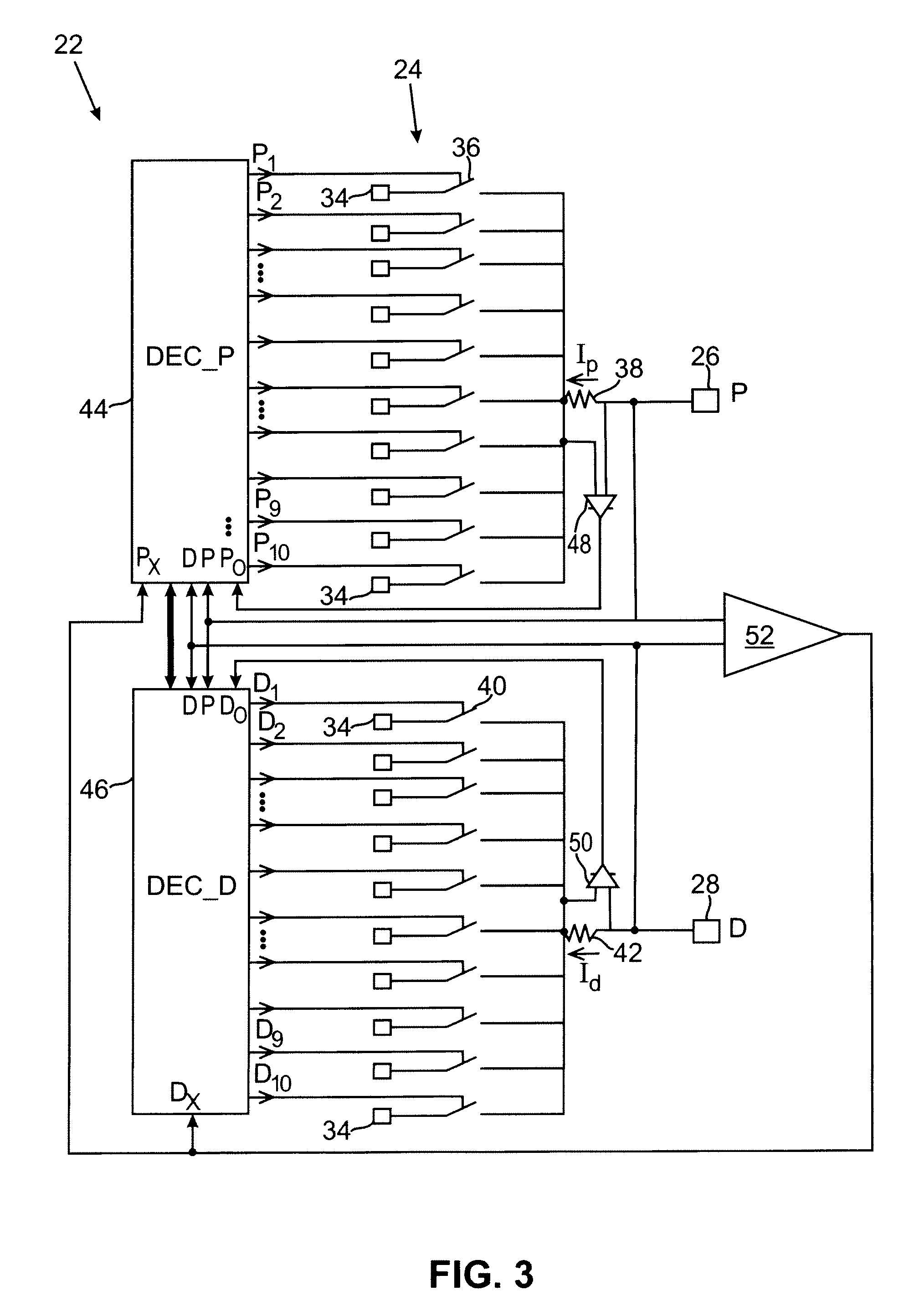
[0030]One will now describe in detail an example embodiment of the device of this invention with reference to the drawings FIGS. 1-6.

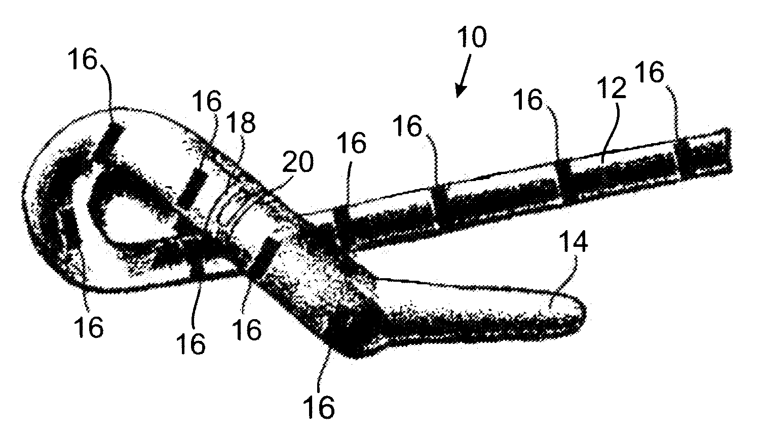
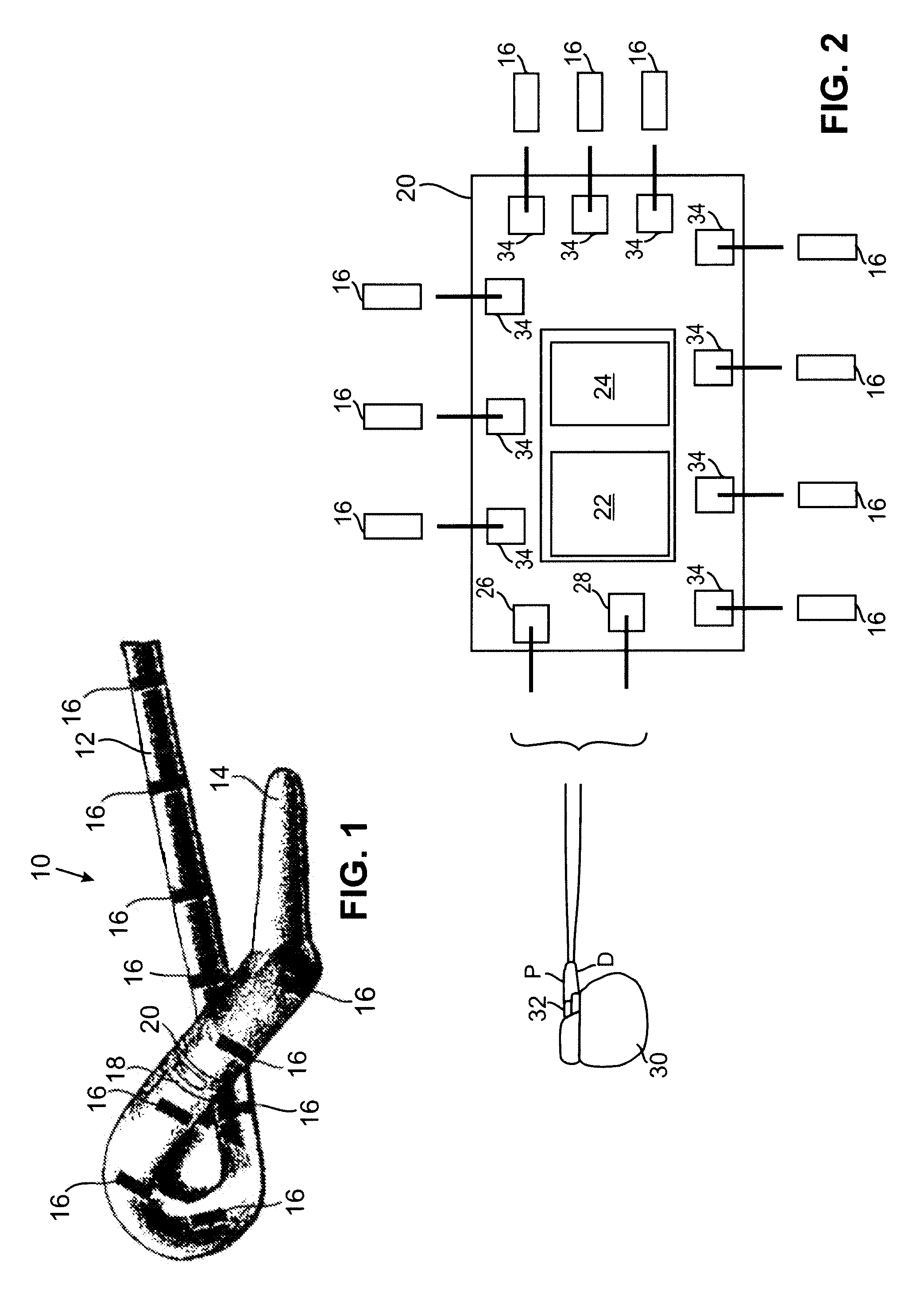
[0031]FIG. 1 schematically represents the extremity of a left ventricular pacing lead, that will be used as an example in the following description. It should be understood however, that this example is, of course, not limiting, and the invention may also apply to other types of endocardial leads (for instance, a sensing / pacing lead in multiple sites of the right ventricle), or to pacing and / or sensing leads, electrodes of which are in contact with other tissues, nerves, muscles, etc.

[0032]The lead 10 is of the general type as described, for example, in U.S. Pat. No. 6,385,492 assigned to ELA Medical, S.A. In the vicinity of the distal tip 14 intended to be introduced in the coronary venous network, the lead body 12 comprises a plurality of electrodes 16, for example, ten electrodes as represented in FIG. 1. The lead also comprises an electronic circui...


PUM


Abstract

A circuit for controlled commutation of multiplexed electrodes, for an active implantable medical device. This circuit is located in a lead equipped with multiplexed sensing / pacing electrodes. This circuit decodes a signal generated by a generator, commanding a series of switches, which ensures selective coupling of the various electrodes to the proximal and distal terminals of the generator. This signal is a modulated signal comprising a coded series of logic pulses defining a particular configuration for coupling the lead electrodes to the proximal or distal terminal of the generator. The signal comprises a micropulse, that precedes the coded series of logic pulses and has an amplitude and duration lower than the amplitude and duration of each of the logic pulses. The detection of this micropulse activates, in response, all the circuit switches to an open position over a duration (PHASE 1) at least equal to the duration of reception of the coded series of logic pulses.

Description

FIELD OF THE INVENTION[0001]The present invention relates to “active medical devices” as such devices are defined by the Jun. 14, 1993 Directive 93 / 42 / CE of the Counsel of the European Community, and more particularly to “active implantable medical devices” as defined by the Jun. 20, 1990 Directive 90 / 385 / CEE of the Counsel of the European Community.[0002]This definition particularly includes devices intended to monitor cardiac activity and schedule and deliver pulses for pacing, resynchronizing, defibrillating and / or cardioverting the heart in response to a rhythm disorder detected by these devices. The definition also includes neurological devices, medical drug diffusion pumps, cochlear implants, implanted biological sensors, etc., as well as pH measurement devices or intracorporeal impedance measurement devices (such as transpulmonary impedance or intracardiac impedance).BACKGROUND OF THE INVENTION[0003]Active implantable medical devices collect signals and deliver pacing pulses ...

Claims


Application Information

Patent Timeline
Patent Type & Authority Applications(United States)
IPC IPC(8): A61N1/365A61B5/296
CPCA61N1/3605A61N1/372A61N1/3627A61N1/36082
Inventor DAL MOLIN, RENZORIPART, ALAIN
Owner SORIN CRM
Learn More