
Side airbag apparatus

a technology of airbags and side airbags, which is applied in the direction of pedestrian/occupant safety arrangements, vehicular safety arrangments, vehicle components, etc., to achieve the effect of reducing the effect of pushing the obstacle by the airbag

Inactive Publication Date: 2008-07-24
TOYODA GOSEI CO LTD
View PDF4 Cites 40 Cited by
  • Summary
  • Abstract
  • Description
  • Claims
  • Application Information

AI Technical Summary

Benefits of technology

[0008]Accordingly, it is an objective of the present invention to provide a side airbag apparatus that, when an obstacle exits in the advancing direction of the airbag deployment, is capable of inflating and deploying the airbag without having any effect on the obstacle by strongly pushing the obstacle.
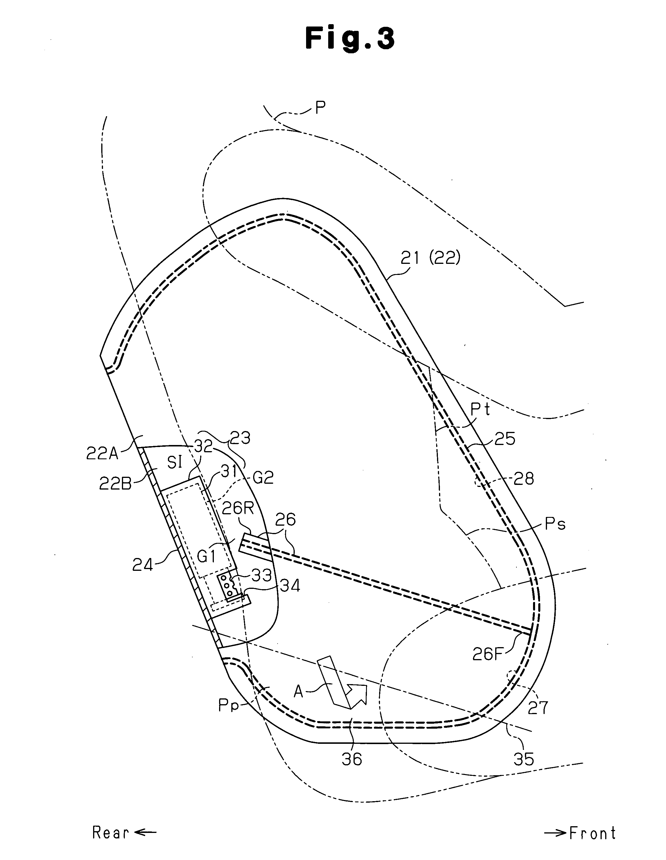
[0012]Accordingly, the area corresponding to the lumbar region protection chamber of the airbag is inflated relatively hard beside the lumbar regions of the occupant. The area corresponding to the protection area of the airbag is deployed relatively softly beside at least either the thorax or the abdominal region of the occupant. By bringing the airbag into contact with each of the parts of the body of the occupant with the hardness in consideration of difference among the parts in resistance to impact, each part of the body of the occupant is effectively protected against the impact.
[0013]Even when an obstacle exists in an advancing direction of the deployment of the airbag and the inflated and deployed airbag contacts the obstacle, the obstacle is pushed by the relatively soft area corresponding to the protection area of a low internal pressure, not by the relatively hard area corresponding to the lumbar region protection chamber of a high internal pressure, until the airbag is completely inflated. Consequently, the effect of pushing the obstacle by the airbag is reduced.

Problems solved by technology

However, in the above-mentioned conventional side airbag apparatus, when a load is put on the seat cushion of the vehicle seat acts as an obstacle in the advancing direction of the airbag deployment, the following problem can occur.

Method used


Image

  • Side airbag apparatus
  • Side airbag apparatus
  • Side airbag apparatus

Examples


Embodiment Construction

[0024]Hereinafter, an embodiment of the present invention will be described with reference to drawings.

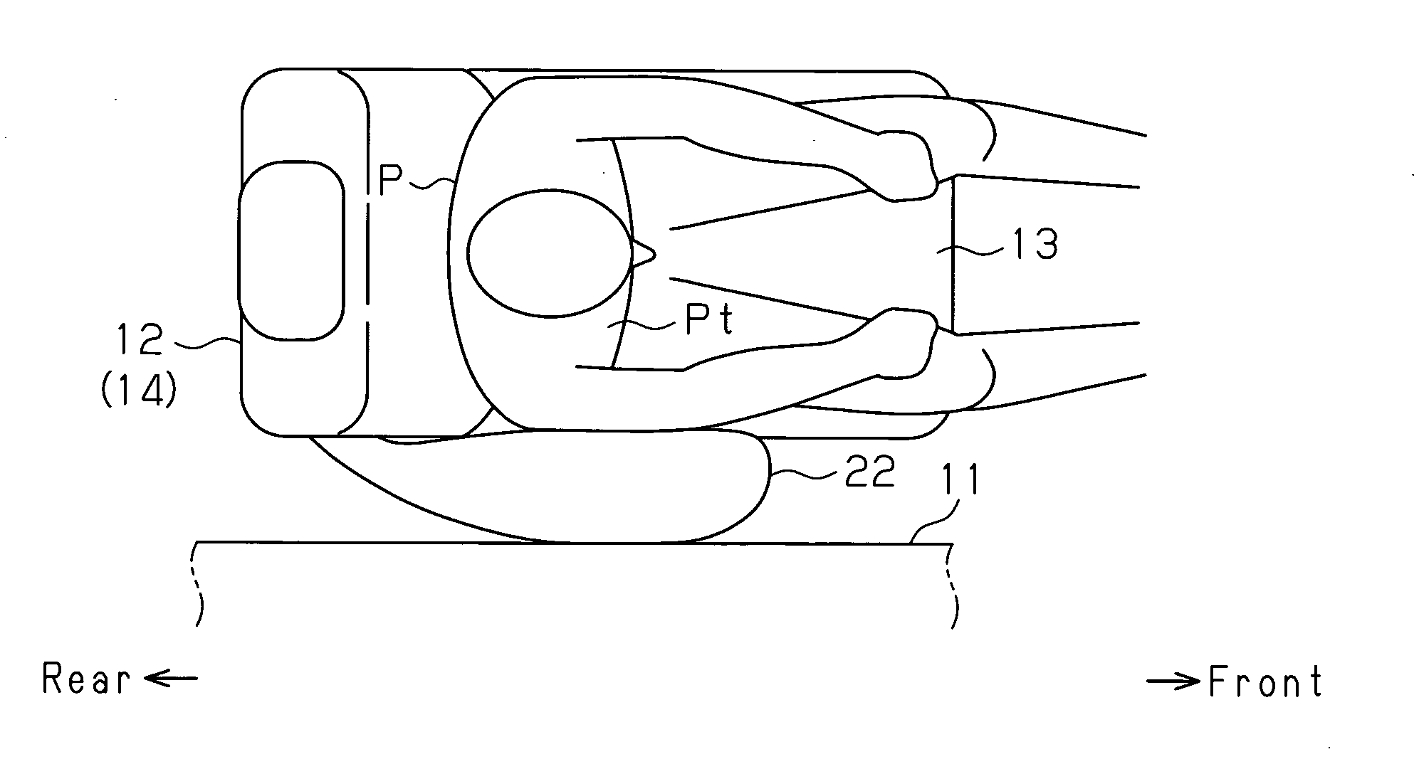
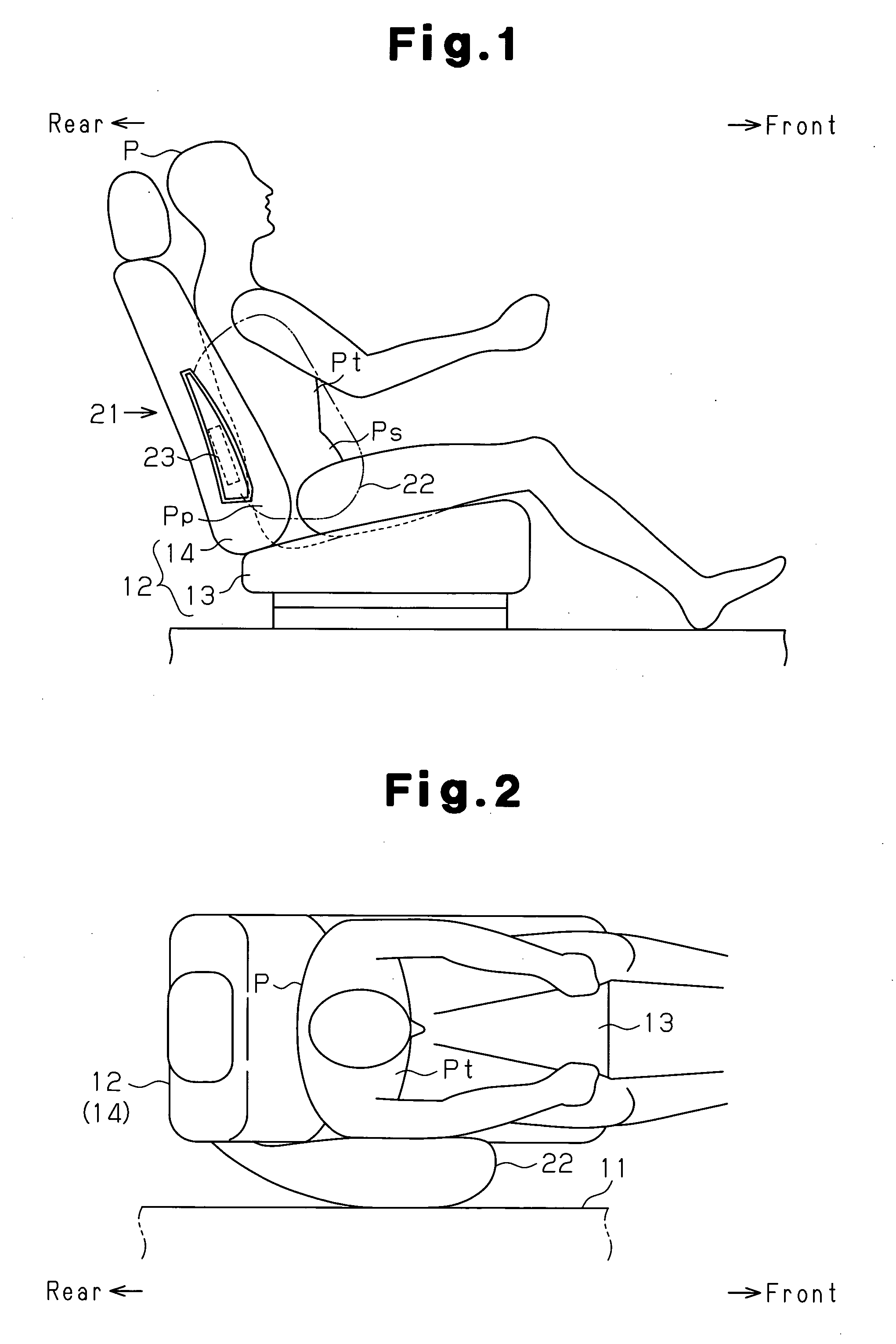
[0025]As shown in FIGS. 1 and 2, a vehicle seat 12 is disposed in the vicinity of a body side portion 11 in a vehicle. The body side portion 11 refers to a member disposed on a side of the vehicle and mainly corresponds to doors and pillars. For example, the body side portion 11 corresponding to a front seat consists of a front door and a center pillar (B pillar). The body side portion 11 corresponding to a rear seat consists of a rear part of a side door (rear door), a C pillar, a front part of a wheel well and a rear quarter panel.

[0026]The vehicle seat 12 has a seat cushion (seat portion) 13 and a backrest 14. An airbag module 21 forming a main part of the side airbag apparatus is incorporated into a side of the backrest 14. The airbag module 21 includes an airbag 22 and an inflator assembly 23 as main components. Next, each of these components will be described. FIG. 3 schemati...


PUM


Abstract

A side airbag apparatus has an inflator 31, an airbag 22, and a tether (partition portion) 26. The tether 26 partitions an internal space SI of the airbag 22 into a lumbar region protection chamber 27 inflated beside lumbar regions Pp of an occupant P and a thorax protection chamber 28 protecting a thorax Pt and an abdominal region Ps. The side airbag apparatus inflates the lumbar region protection chamber 27 at a higher internal pressure than the thorax protection chamber 28. In the side airbag apparatus, the tether 26 is disposed in the internal space SI so as to be inclined downward toward the front of the vehicle. The area corresponding to the lumbar region protection chamber 27 of the airbag 22 is folded along the inclination of the tether 26.

Description

BACKGROUND OF THE INVENTION[0001]The present invention relates to a side airbag apparatus which inflates and deploys an airbag when an impact is applied to a vehicle from a side and reduces the impact by the airbag to protect an occupant.[0002]A side airbag apparatus is widely known as an apparatus for protecting an occupant in a vehicle when receiving impact from a side as in a side collision impact. The side airbag apparatus includes an inflator and an airbag. The airbag is incorporated into a backrest of a vehicle seat in a compact folded fashion.[0003]In the side airbag apparatus, when an impact is applied to a body side portion of the vehicle from a side, the inflator is activated and ejects gas into the airbag. The airbag, into which gas is ejected, is inflated and deployed frontward from the backrest in a narrow space between an occupant seated in the vehicle seat and the body side portion. The inflated airbag is interposed between the occupant and the body side portion intru...

Claims


Application Information

Patent Timeline
IPC IPC(8): B60R21/237B60R21/207B60R21/20B60R21/233B60R21/2338
CPCB60R21/207B60R21/23138B60R21/233B60R2021/23382B60R21/237B60R2021/23324B60R21/2338
Inventor INOUE, MICHIO
Owner TOYODA GOSEI CO LTD
Learn More