
Flat type wave gear device

a gear device and wave technology, applied in the direction of gearing, gearing elements, hoisting equipment, etc., can solve the problems of no studies relating to the design optimization of the rim thickness of the flexible external gear the small load capacity of the flat type wave gear device, so as to increase optimize the rim thickness. , the effect of increasing the strength of the tooth roo

Active Publication Date: 2008-07-24
HARMONIC DRIVE SYST IND CO LTD
View PDF2 Cites 19 Cited by
  • Summary
  • Abstract
  • Description
  • Claims
  • Application Information

AI Technical Summary

Benefits of technology

[0012]In view of the foregoing, the purpose of the present invention is to endeavor to optimize the rim thickness of the flexible external gear to greatly improve the load capacity of the flat type wave gear device.
[0013]The present inventors made it possible to more than double the previous fatigue strength of the tooth root of the flexible external gear by obtaining the optimal rim thickness of the flexible external gear produced by the bending deformation by the elliptically shaped wave generator and the tensile deformation due to load torque, and by setting a suitable hardness for the material of the flexible external gear.
[0018]In accordance with this invention, it is possible to increase the tooth root strength by optimizing the rim thickness of the flexible external gear of the flat type wave gear device subjected to bending deformation and tensile deformation. It is also possible to greatly increase the tooth root strength by optimizing the rim thickness of the flexible external gear and optimizing the hardness of the material thereof. As a result, in accordance with this invention, it is possible to realize a flat type wave gear device having a much higher load capacity than before.

Problems solved by technology

Compared to other types such as the cup and silk-hat types, the utility of a flat type wave gear device is limited by its small load capacity.
However, previously there have been no studies relating to design optimization of the rim thickness of the flexible external gear of a flat type wave gear device.

Method used


Image

  • Flat type wave gear device
  • Flat type wave gear device
  • Flat type wave gear device

Examples


Embodiment Construction

[0025]Details of the present invention are described below, with reference to the drawings.

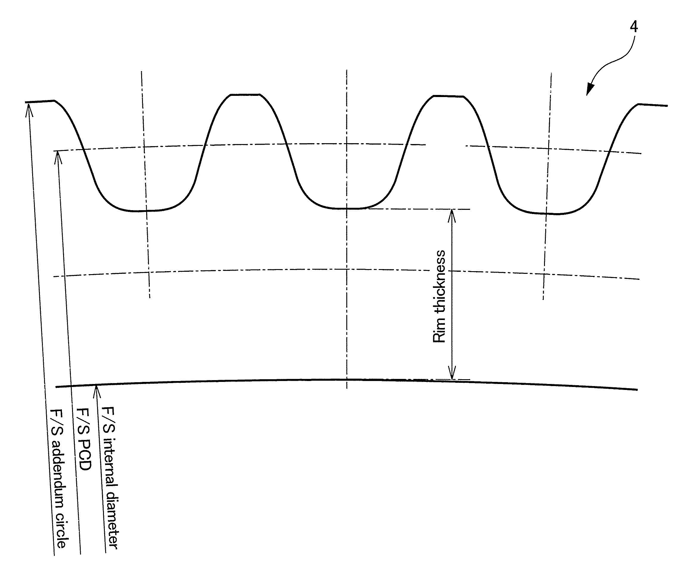
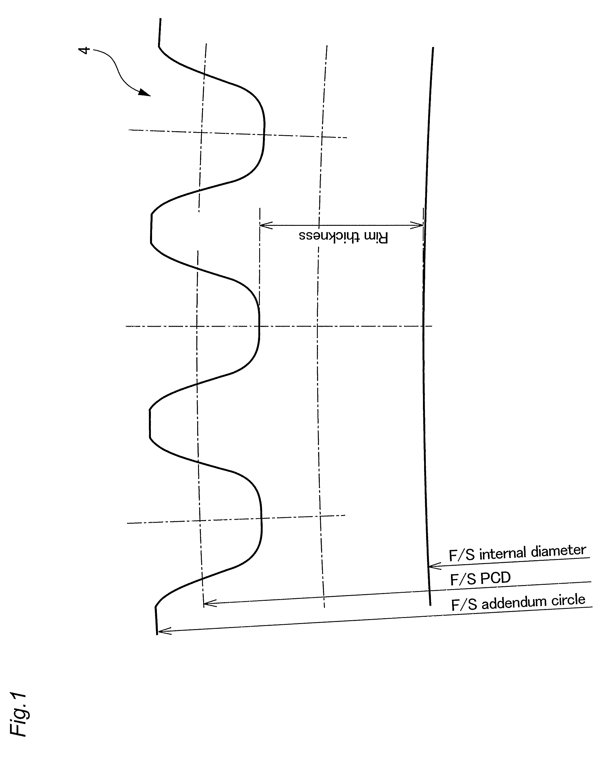
[0026]FIG. 6 shows the configuration of a flat type wave gear device to which the present invention may be applied. FIG. 1 is a conceptual diagram showing the rim thickness of an annular flexible external gear (F / S) 4 of the flat type wave gear device 1; in the diagram, the rim thickness is the thickness of the portion denoted by t. Also, the radial flexing amount d of the flexible external gear 4 flexed into an elliptical shape by the wave generator 5, is the amount of radial flexing at a major axis location on the rim neutral circle thereof. With n being the difference between the number of teeth of the flexible external gear 4 and rigid internal gear 3 and m being the module of the flexible external gear 4, this radial flexing amount d is d=mn.

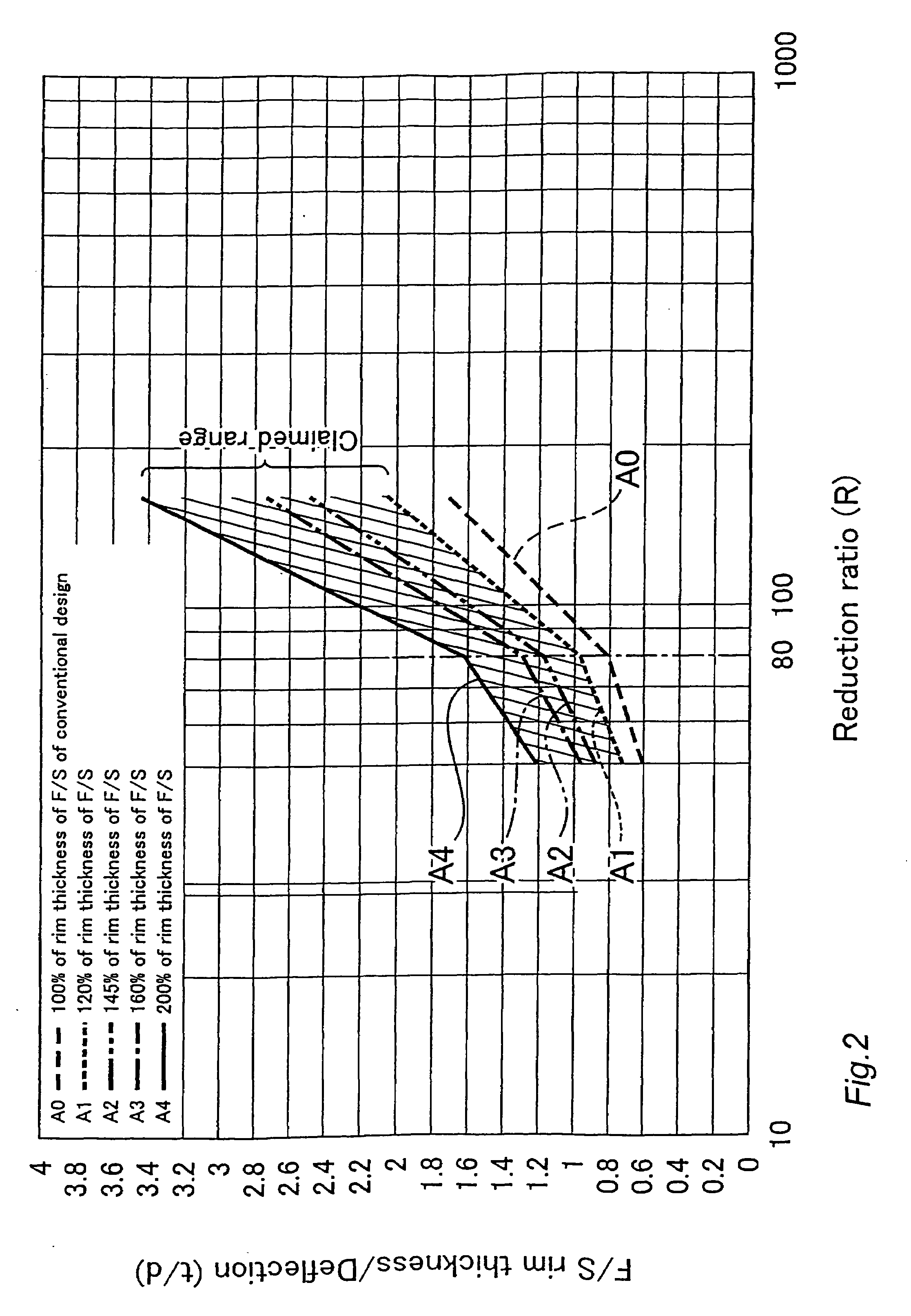
[0027]FIG. 2 is a graph showing the rim thickness prescribed by the present invention, and the rim thickness of the flexible external gear (F / S) of a...


PUM


Abstract

A flat type wave gear device is realized having a much improved load capacity. When d is an amount of radial flexing at a major axis location of a rim neutral circle of the flexible external gear of a flat type wave gear device flexed into an elliptical shape and t is the rim thickness of the flexible external gear, then(0.5237 Ln(R)−1.32)d≦t≦(0.8728 Ln(R)−2.2)d when the reduction ratio R of the wave gear device is less than 80, and(1.5499 Ln(R)−5.8099)d≦t≦(2.5832 Ln(R)−9.6832)d when the reduction ratio R of the wave gear device is 80 or more. Using this setting makes it possible to increase the tooth root fatigue limit strength of the flexible external gear, thereby making it possible to improve the load capacity of the flexible external gear.

Description

TECHNICAL FIELD[0001]The present invention relates to a flat type wave gear device equipped with an annular flexible gear with external teeth, and more particularly, to an improved technology for increasing the tooth root strength with the object of increasing the load capacity of the flat type wave gear device.BACKGROUND ART[0002]A wave gear device is equipped with a rigid internal gear, a flexible external gear disposed inside the rigid internal gear, and a wave generator that flexes the flexible external gear into an elliptical shape, causing it to partially mesh with the rigid internal gear. When the wave generator is rotated by a motor or the like, the position at which both gears mesh moves circumferentially, generating a reduced-speed relative rotation between the two gears that corresponds to the difference in the number of the two gears' teeth. By fixing one gear so that it does not rotate, it is possible to output and transmit reduced-speed rotation from the other gear to ...

Claims


Application Information

Patent Timeline
IPC IPC(8): F16H33/00
CPCF16H49/001Y10T74/19Y10T74/19967F16H2049/003
Inventor ZHANG, XIN YUEUEURA, KEIJI
Owner HARMONIC DRIVE SYST IND CO LTD
Learn More