Adapter for cutting tooth

a technology for adapters and teeth, applied in soil-shifting machines/dredgers, construction, etc., can solve the problems of mounting blocks, damage to cutting teeth, and relatively expensive replacement of teeth, and achieve the effect of facilitating replacement and facilitating replacemen

Inactive Publication Date: 2008-07-24
DENIS LAURENT
View PDF36 Cites 13 Cited by
  • Summary
  • Abstract
  • Description
  • Claims
  • Application Information

AI Technical Summary

Benefits of technology

[0005]It is the purpose of the present invention to provide an adapter which can be mounted between the tooth and the mounting block when mounting the tooth on the block. The adapter is relatively inexpensive and is made of material allowing it to deform more readily than the tooth or block if the assembly strikes a rock or similar hard object. If a rock is struck, it is more likely that the softer adapter will be damaged or deformed rather than the harder tooth or mounting block and the inexpensive adapter can be readily replaced.
[0009]If the assembled mounting on the cutter head hits a rock or boulder during operation of the head, the softer adapter will often deform before the tooth or the block are damaged. The cutting tooth may be slightly displaced when the adapter is deformed but would still be operational though not as efficiently. The deformed adapter can be easily replaced. The replacement adapter correctly realigns the cutting tooth with the mounting block for maximum efficiency. The adapters are relatively inexpensive compared to the teeth or the block so considerable savings can be achieved by the using the adapters without lowering the efficiency of the machine. assembly for mounting cutting teeth on a cutter head which mounting assembly reduces damage to the teeth and blocks during operation and reduces the operating cost of the machine. The mounting assembly has a mounting block fixedly mountable on the cylindrical surface of a brush cutter drum, the mounting block having a front side. A thin adapter is detachably mounted on the front side of the block and a cutting tooth is detachably mounted against the adapter, the adapter aligning the tooth with the front side of the block. The tooth is fastened to the block with a bolt, the bolt passing through the adapter.

Problems solved by technology

The cutting heads often operate in an environment where rocks or boulders are present and these rocks or boulders are frequently hit by the cutting head.
These hits can severely damage the cutting teeth and / or the mounting blocks on the head.
The damaged teeth are relatively expensive to replace and the mounting blocks, if damaged, are even more expensive to replace since they are normally welded onto the drum.

Method used


Image

  • Adapter for cutting tooth
  • Adapter for cutting tooth
  • Adapter for cutting tooth

Examples


Embodiment Construction

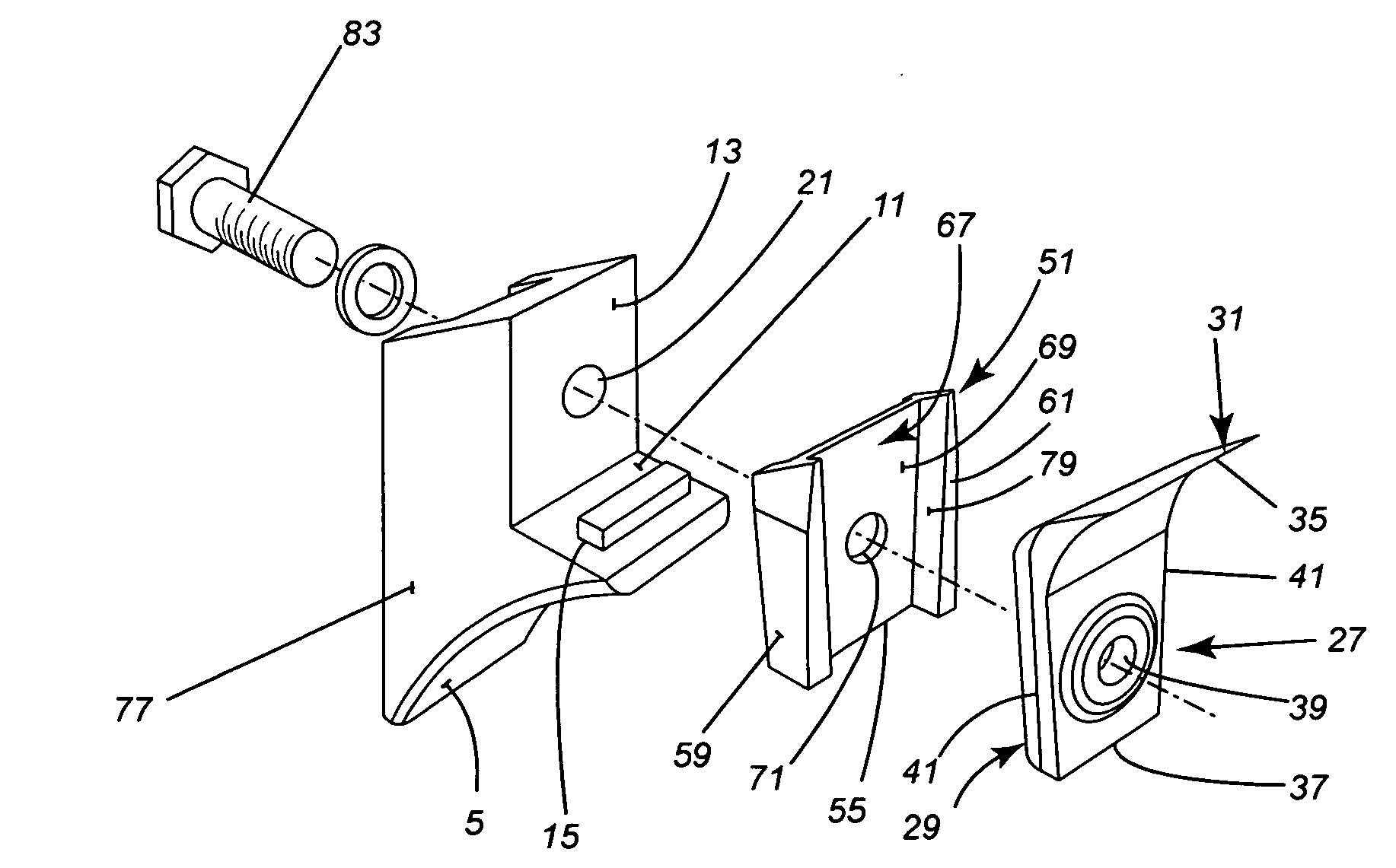
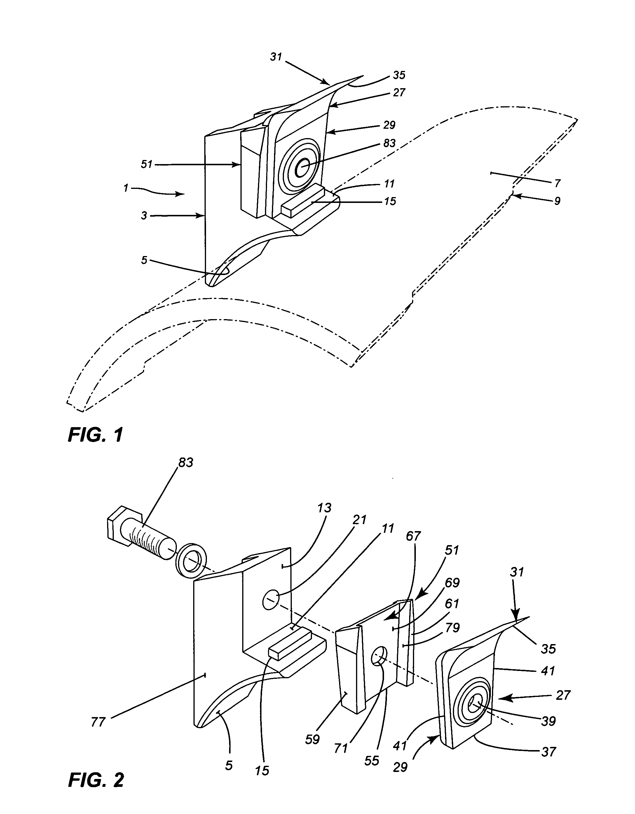
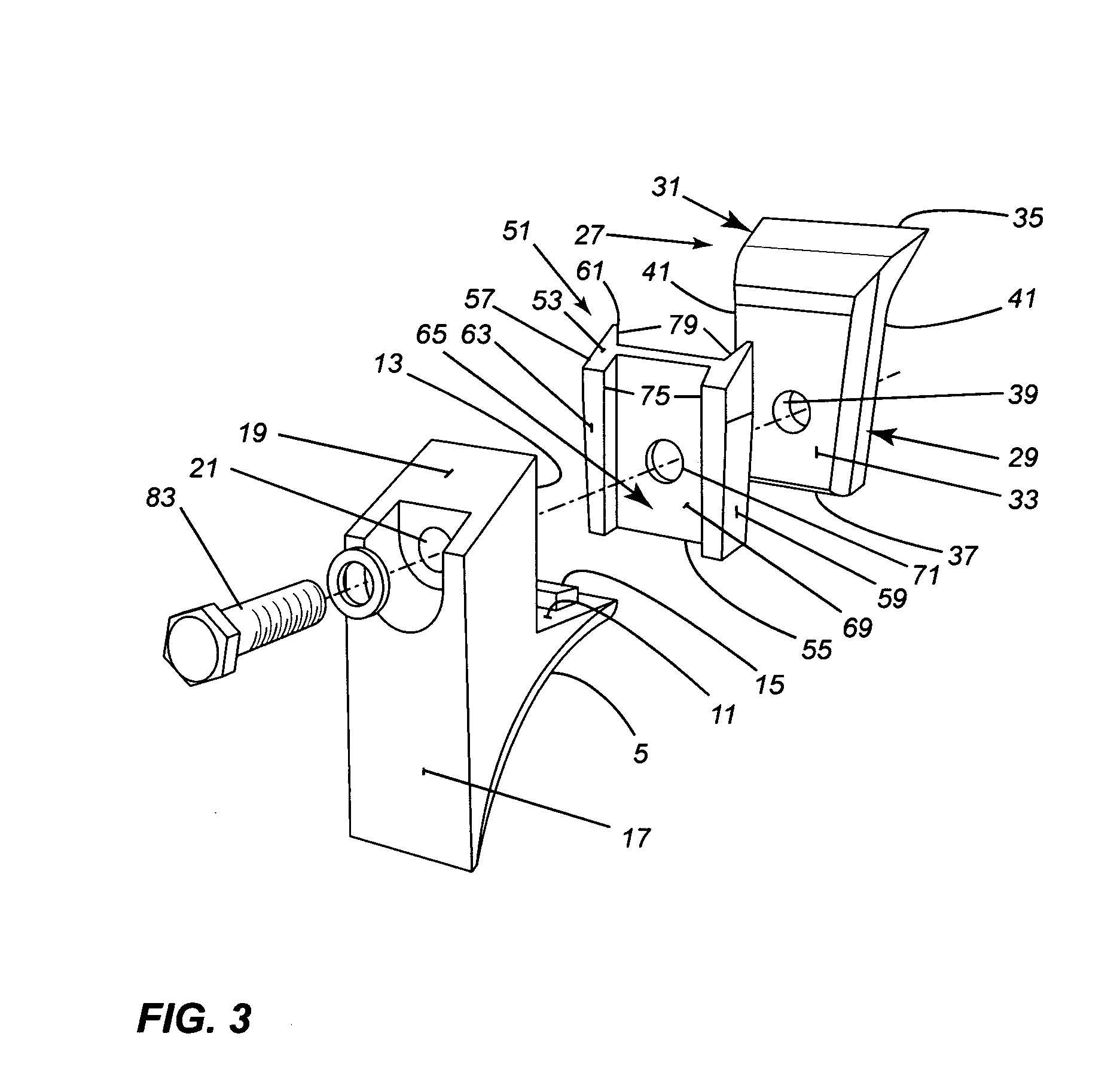
[0016]The mounting assembly 1 of the present invention, as shown in FIGS. 1, 2 and 3, includes a mounting block 3 having a bottom side 5, slightly concave, by means of which it is attached to the surface 7 of a cylindrical, rotatable, cutter head 9. The mounting block 3 is attached, usually by welding, to the surface 7 to be transverse to the longitudinal, rotational axis of the cylindrical head 9. The mounting block 3 has a step 11 just above the front of the bottom side 5 and a front side 13 extending up from the step 11. A stop rib 15 can extend up from the step 11, spaced from the front side 13 and parallel to it. The block has a back side 17 extending up from the rear of the bottom side 5. The back side 17 can be parallel to the front side 13. A top side 19, which angles upwardly, joins the top of back side 17 to the top of the front side 13. A bolt hole 21 extends through the block from the back side 17 to about the center of the front side 13. When the block 3 is mounted on t...


PUM


Abstract

An adapter for use in mounting a cutting tooth onto a mounting block. The adapter has two opposed sides with a first groove on one side for receiving a leading portion of the mounting block and a second groove on the other side opposite the one side for receiving a portion of the cutting tooth. The first and second grooves are aligned. The adapter has a fastening hole there through in the grooves, the hole transverse to the sides of the adapter. The fastening hole is used in fastening the tooth to the mounting block with the adapter sandwiched between the tooth and mounting block.

Description

BACKGROUND OF THE INVENTION[0001]1. Technical Field[0002]This invention is directed toward an adapter for use in mounting a cutting tooth used on a rotating cutting head. The invention is also directed toward a cutting tooth mounting assembly for use on a rotating cutting head.[0003]2. Background Art[0004]Rotating cutting heads, such as heads on brush cutters, have a plurality of cutting teeth mounted over the surface of the head. Each tooth is detachably mounted on a mounting block which block in turn is fixedly mounted on the surface of the cylindrical head of the cutter. The tooth is normally fixed by a bolt directly to the block so it can be easily replaced if damaged or broken. The cutting heads often operate in an environment where rocks or boulders are present and these rocks or boulders are frequently hit by the cutting head. These hits can severely damage the cutting teeth and / or the mounting blocks on the head. The damaged teeth are relatively expensive to replace and the ...

Claims


Application Information

Patent Timeline
Patent Type & Authority Applications(United States)
IPC IPC(8): E02F9/28
CPCE02F9/2866E02F9/2825
Inventor DENIS, LAURENT
Owner DENIS LAURENT
Why Eureka
Try Eureka