
System for predicting driver behavior

a technology for predicting driver behavior and vehicle movement, applied in the field of vehicle movement and behavior, can solve the problems of fixed thresholds producing either too many false positives or not enough warning, their overall reliability and effectiveness is limited, and collisions are a very complicated computation

Inactive Publication Date: 2008-07-10
TOYOTA INFOTECHNOLOGY CENT CO LTD
View PDF3 Cites 87 Cited by
  • Summary
  • Abstract
  • Description
  • Claims
  • Application Information

AI Technical Summary

Benefits of technology

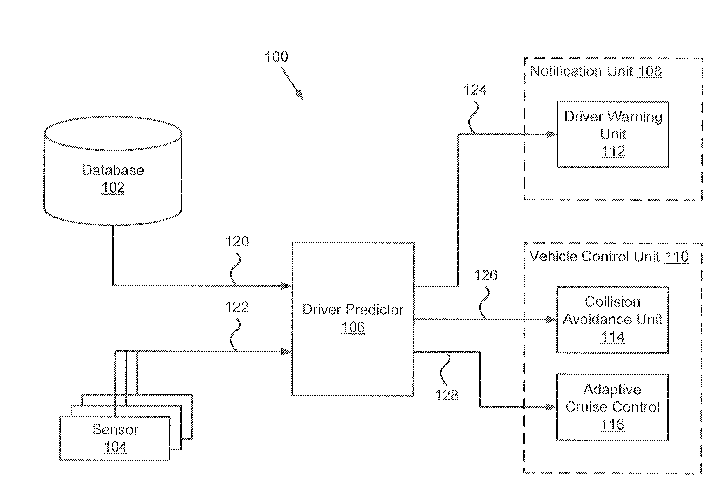
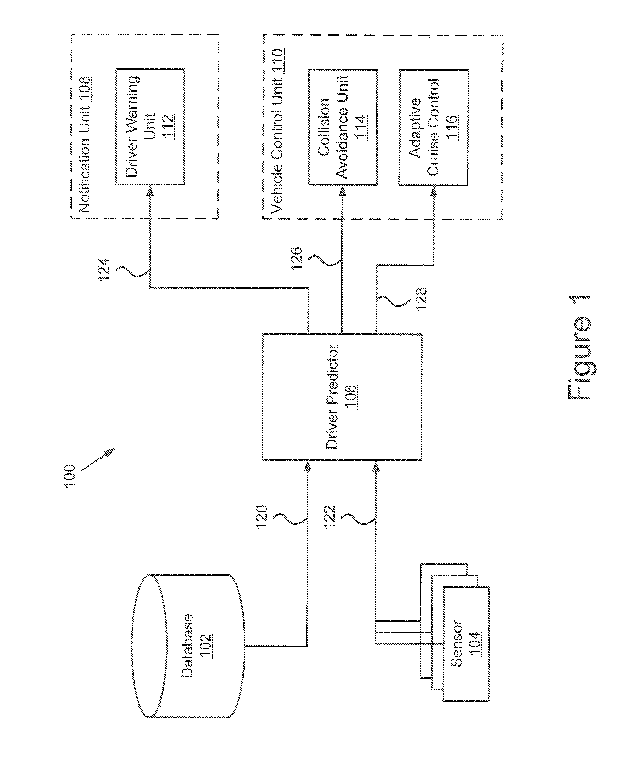
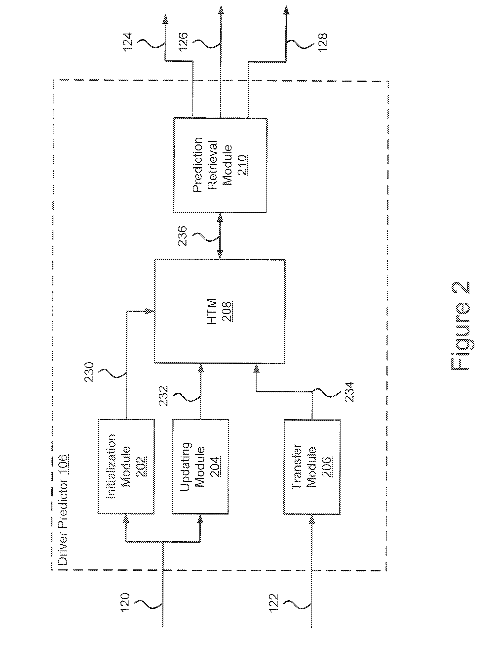
[0008]The present invention overcomes the deficiencies and limitations of the prior art by providing a system and method for predicting driver behavior and generating control and/or warning signals. In one embodiment, the system comprises: one or more sensors; a database; a driver predictor for generating warning and control signals; a notification unit; and a vehicle control unit. More specifically, the driver predictor includes a transfer module, a hierarchical temporal memory and a prediction retrieval module. The transfer module is used to receive data and translate it into a form so that it can be stored in the hierarchical temporal memory. The hierarchical temporal memory advantageously includes three levels of memory one for short-term, one for intermediate term and one for long term. The hierarchical temporal memory advantageously receives data input and stores it such

Problems solved by technology

However, one problem with such prior art methods is that fixed thresholds produce either too many false positives or not enough warning.
Thus, their overall reliability and effectiveness is limited which has precluded their adoption.
Another problem is that predicting the conditions that are likely to result in a collision is a very complicated computation.
However, the problem with using neural networks in this way is that the predictions are not accurate because there is no way to include user intention or driving habits in the models.

Method used


Image

  • System for predicting driver behavior
  • System for predicting driver behavior
  • System for predicting driver behavior

Examples


Embodiment Construction

[0017]A system and method for predicting driver behavior and generating control and / or warning signals is described. In the following description, for purposes of explanation, numerous specific details are set forth in order to provide a thorough understanding of the invention. It will be apparent, however, to one skilled in the art that the invention can be practiced without these specific details. In other instances, structures and devices are shown in block diagram form in order to avoid obscuring the invention. For example, the present invention is described in one embodiment below with reference to a java, user interfaces and particular hardware. However, the present invention applies to any type of computing device that can receive a data and commands, and any peripheral devices providing services.

[0018]Reference in the specification to “one embodiment” or “an embodiment” means that a particular feature, structure, or characteristic described in connection with the embodiment ...


PUM


Abstract

A system and method for predicting driver behavior and generating control and / or warning signals comprises: one or more sensors; a database; a driver predictor for generating warning and control signals; a notification unit; and a vehicle control unit. More specifically, the driver predictor includes a transfer module, a hierarchical temporal memory and a prediction retrieval module. The transfer module is used to receive data and translate it into a form so that it can be stored in the hierarchical temporal memory. The hierarchical temporal memory receives data input and stores it such that data items are translated into short-term memory items which are in turn translated into intermediate-term data which in turn are finally translated into long-term data. The translation of data from one level of the memory to another is performed according to the present invention such that the data at each level of memory is reflective of and predictive of a particular driver behavior. Once the data is stored in the memory, the prediction retrieval module accesses the hierarchical temporal memory to generate warning signals to alert the driver of potentially dangerous conditions and / or control systems of the vehicle to prevent or avoid collisions. The present invention also includes a variety of method including a method for storing driving data in a hierarchical temporal memory, and a method for using a hierarchical temporal memory to generate collision avoidance signals.

Description

CROSS-REFERENCE TO RELATED APPLICATIONS[0001]This application claims the benefit under 35 U.S.C. § 119(e) of provisional patent application Ser. No. 60 / 883,452 filed Jan. 4, 2007 by the present inventors.BACKGROUND OF THE INVENTION[0002]1. Field of the Invention[0003]The present invention relates to vehicle movement and behavior, and in particular, to a system for predicting vehicle movement or behavior. Still more particularly, the present invention relates to systems and methods of predicting vehicle movement or behavior of other vehicles in the proximity of a primary vehicle.[0004]2. Description of the Background Art[0005]The prior art includes a variety of systems related to collision detection or crash warning. Many receive sensor signals and determine whether the signals are greater than a threshold, and if so they send a warning or send a control signal to modify operation of the vehicle. However, one problem with such prior art methods is that fixed thresholds produce either...

Claims


Application Information

Patent Timeline
IPC IPC(8): G08G1/16G06F17/10
CPCB60W30/08B60W30/09B60W30/16B60W30/18163B60W40/09B60W40/107G08G1/16B60W2050/0029B60W2050/0057B60W2050/143B60W2420/52B60W2540/30B60W50/12G08G1/166G08G1/167
Inventor OGUCHI, KENTAROWEIR, DAVID
Owner TOYOTA INFOTECHNOLOGY CENT CO LTD
Learn More