
Method and apparatus for reduction of metal artifacts in ct imaging

a computed tomography and artifact technology, applied in tomography, instruments, applications, etc., can solve problems such as artifacts, reconstructed images with artifacts, dark and bright streaks, etc., and achieve the effect of reducing artifacts in image data

Inactive Publication Date: 2008-07-10
GENERAL ELECTRIC CO
View PDF15 Cites 19 Cited by
  • Summary
  • Abstract
  • Description
  • Claims
  • Application Information

AI Technical Summary

Benefits of technology

[0007]The present invention recites a method and apparatus for reducing artifacts in image data caused by high density objects.

Problems solved by technology

One problem with reconstructed images in CT systems is artifacts caused by the presence of high density objects, for example, metal objects in a subject.
The presence of such high density objects in a subject causes relatively high attenuation of the X-ray beams as they propagate through the subject, thereby resulting in a reconstructed image with artifacts.
These artifacts can produce significant dark and bright streaks in the reconstructed image that severely limit the CT assessment of soft tissue and bone structures surrounding the high density objects.
Polynomial correction also has its limits however, as it works well only when the high density object in the patient is comprised of a homogenous material.
A disadvantage of all the above techniques is that they result in either only a partial reduction of artifacts, introduce new artifacts, have a high computation time, or result in the formation of blurred images.

Method used


Image

  • Method and apparatus for reduction of metal artifacts in ct imaging
  • Method and apparatus for reduction of metal artifacts in ct imaging
  • Method and apparatus for reduction of metal artifacts in ct imaging

Examples


Embodiment Construction

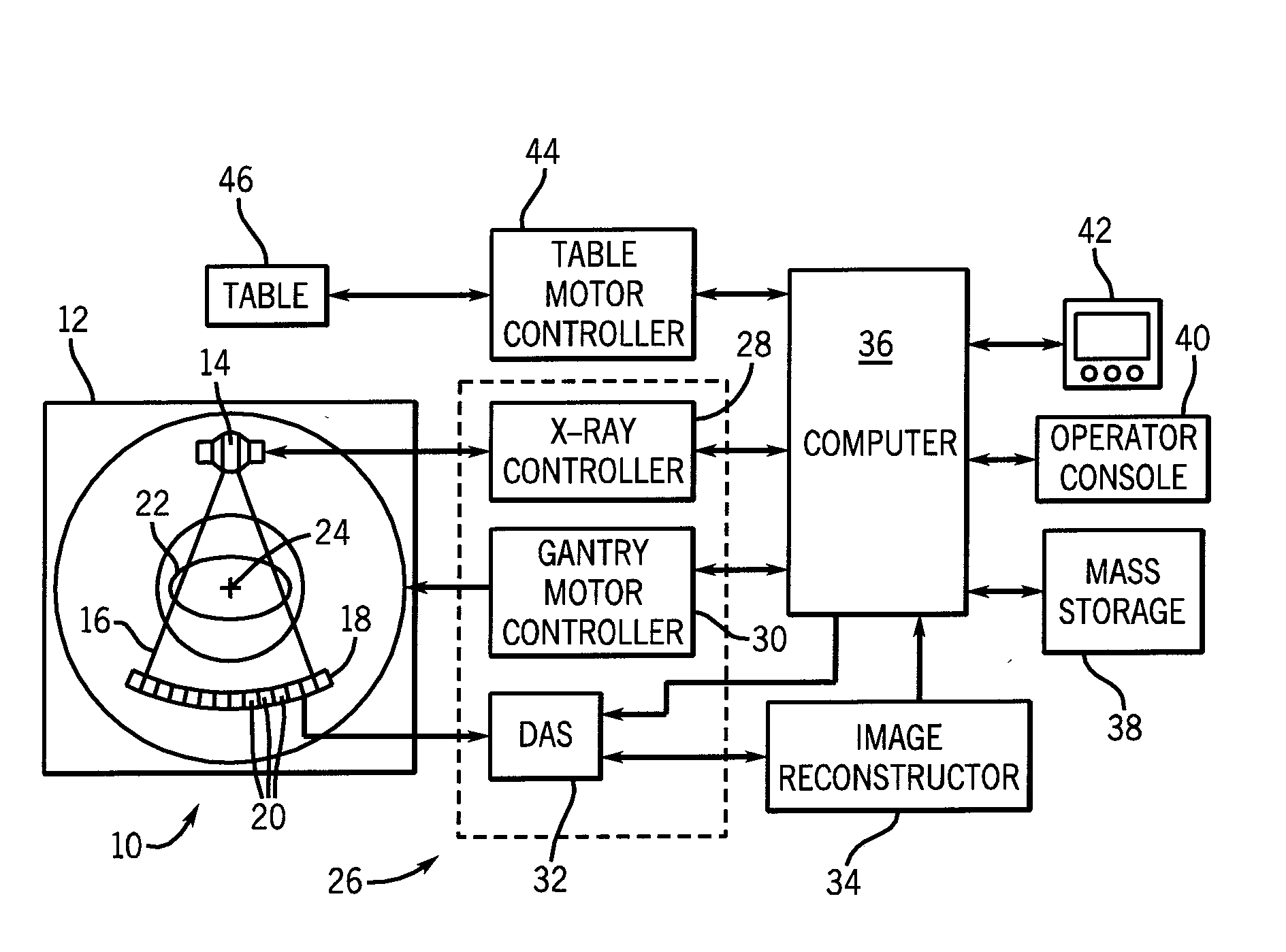
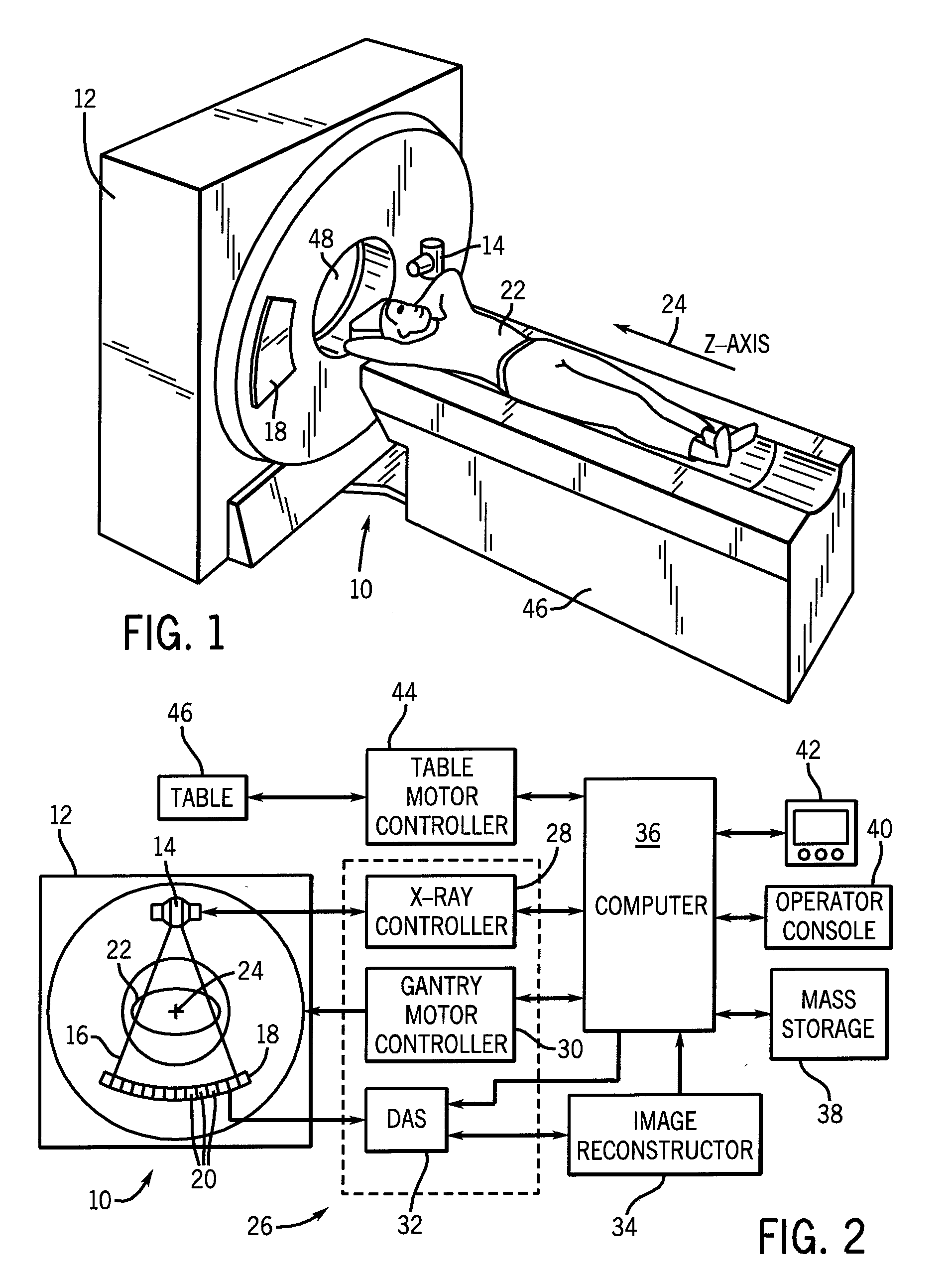
[0019]Referring to FIGS. 1 and 2, an embodiment of a computed tomography (CT) imaging system 10 is shown as including a gantry 12 representative of a “third generation” CT scanner. Gantry 12 has an x-ray source 14 that projects a beam of x-rays 16 toward a detector assembly 18 on the opposite side of the gantry 12. Detector assembly 18 is formed by a plurality of detectors 20 which together sense the projected x-rays that pass through a medical patient 22. Each detector 20 produces an electrical signal that represents not only the intensity of an impinging x-ray beam but is also capable of providing photon or x-ray count data, and hence the attenuated beam as it passes through the patient 22. During a scan to acquire x-ray projection data, gantry 12 and the components mounted thereon rotate about a center of rotation 24.

[0020]Rotation of gantry 12 and the operation of x-ray source 14 are governed by a control mechanism 26 of CT system 10. Control mechanism 26 includes an x-ray contr...


PUM


Abstract

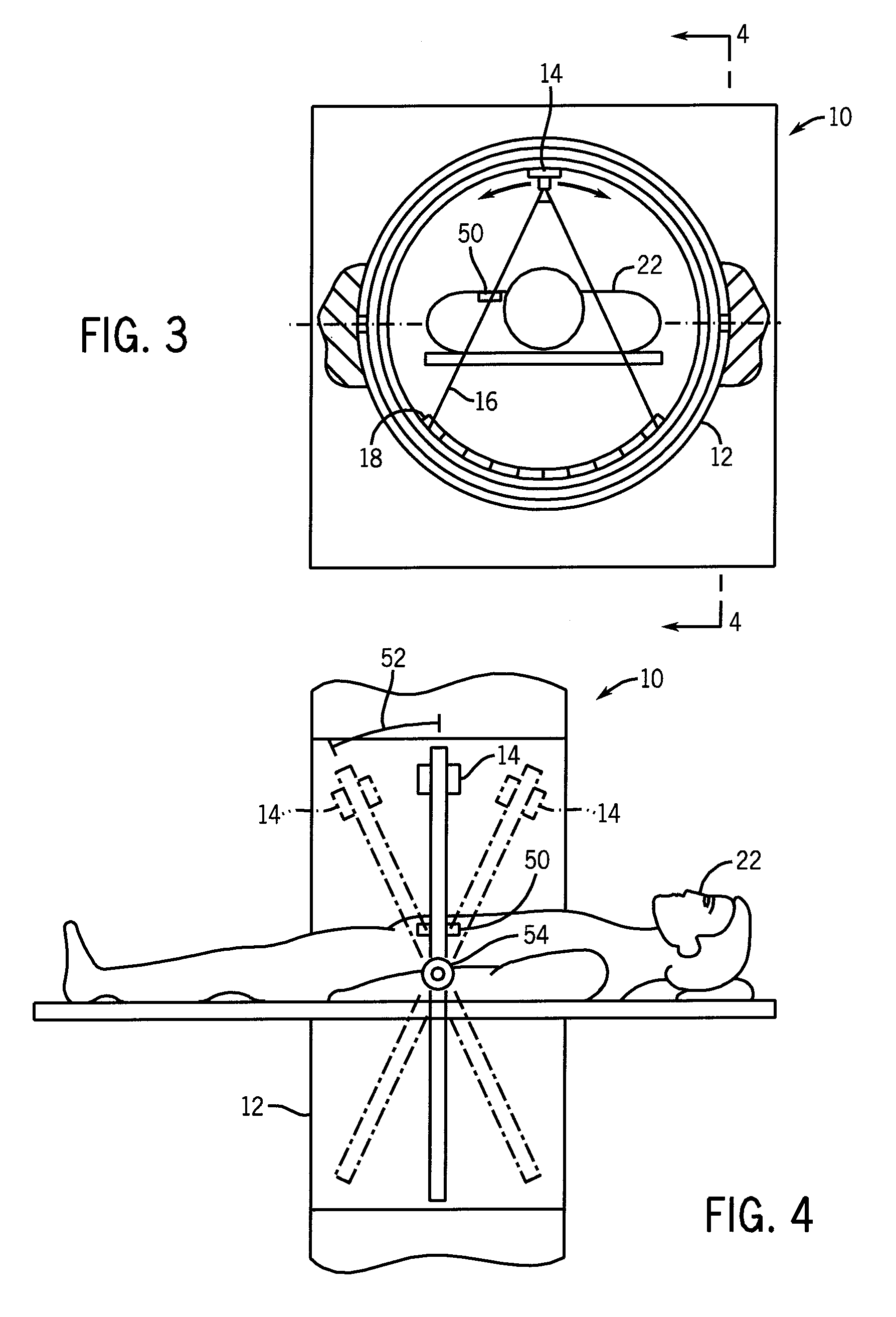
A method and apparatus for reducing artifacts in image data generated by a computed tomography system is provided. The artifacts are due to the presence of a high density object in a subject of interest. CT data is acquired at a number of differing tilt angles. The data is then combined and reconstructed to generate an improved composite image substantially free of artifacts caused by the high density object.

Description

BACKGROUND OF THE INVENTION[0001]The present invention generally relates to the field of image reconstruction in computed tomography (CT) systems and more particularly to a method and apparatus for reducing artifacts in image data caused by high density objects.[0002]CT scanners operate by projecting fan shaped or cone shaped X-ray beams through an object. The X-ray beams are generated by an X-ray source, and are generally collimated prior to passing through the object being scanned. The attenuated beams are then detected by a set of detector elements. The detector elements produce a signal based on the intensity of the attenuated X-ray beams, and the signals are processed to produce projections. By using reconstruction techniques, such as filtered backprojection, useful images are formed from these projections.[0003]A computer is able to process and reconstruct images of the portions of the object responsible for the radiation attenuation. As will be appreciated by those skilled in...

Claims


Application Information

Patent Timeline
IPC IPC(8): A61B6/03G06K9/00
CPCA61B6/4241A61B6/5282A61B6/482A61B6/4447
Inventor DE MAN, BRUNO K. B.WALTER, DEBORAH JOY
Owner GENERAL ELECTRIC CO
Learn More