
Systems for self-balancing control of mixing and pumping

Active Publication Date: 2008-07-10
HALLIBURTON ENERGY SERVICES INC
View PDF19 Cites 63 Cited by
  • Summary
  • Abstract
  • Description
  • Claims
  • Application Information

AI Technical Summary

Benefits of technology

[0007]The control system can be designed to remain stable and avoid oscillations within a range of specific operating conditions. A well-designed control system can significantly reduce the need for human intervention, even during upset conditions in an operating process.
[0017]The disclosed innovations, in various embodiments provide one or more of at least the following advantages:

Problems solved by technology

But sometimes, the amount of instrumentation available at well service sites is limited.
However, solids flow meters, such as a weigh belt feeder, are much more difficult to service and to keep in calibration.
So, the control system is faced with a challenge as to how to monitor flow rates of a powdered solid, such as cement, without actually measuring the flow rate.
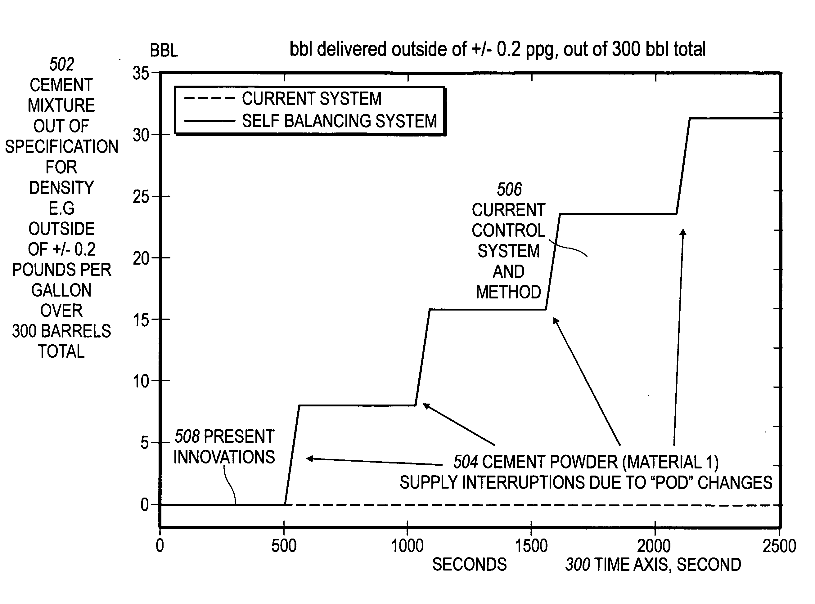
Sometimes, supply of a particular component can get interrupted momentarily or constrained somehow (e.g. a supply constraint), and can cause a control disturbance to an automatic control system controlling the supply valve actuators and pumping system.
For example, dry cement can be supplied from unitized storage systems, e.g. “pods”, that require change-over when they become empty, and thus, momentary interruption of the supply of dry cement can occur.
For another example, the flow rate of a particular material can be unintentionally and / or unknowingly restricted due to a partial blockage of a supply line.
For example, dry cement can pick-up moisture and begin to coat the interior of pipes, or collect at conduit elbows or valves, resulting in a restriction.
When a supply interruption or constraint occurs, the control system can be faced with a challenge, especially when limited flow rate information is available, as to how to best react to balance quality control of the service fluid, e.g. density control, and the required supply rate, e.g. barrels per minute of fluid demanded down-hole.
A material supply constraint can be a limitation in the availability of supply of the materials.

Method used


Image

  • Systems for self-balancing control of mixing and pumping
  • Systems for self-balancing control of mixing and pumping
  • Systems for self-balancing control of mixing and pumping

Examples


Embodiment Construction

[0039]The numerous innovative teachings of the present application will be described with particular reference to the presently preferred embodiment (by way of example, and not of limitation).

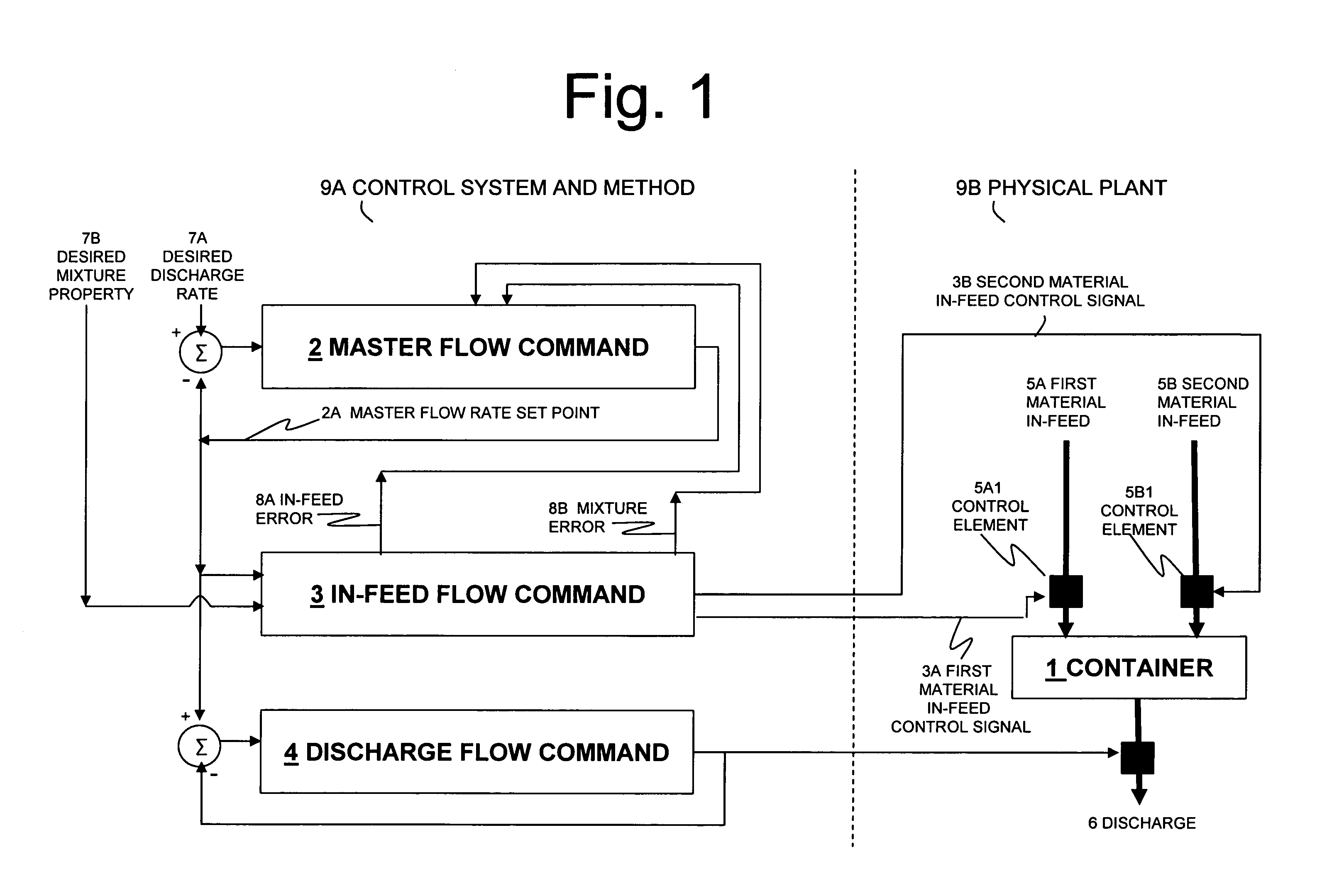
[0040]FIG. 1 shows one embodiment of the present innovations comprised of control system and method 9A and physical plant 9B. A desired discharge flow rate 7A can be inputted into control system and method 9A for the mixture discharge flow rate out of container 1. A desired value for a property of the mixture 7B can be inputted as well.

[0041]Master flow command 2 can provide a master flow rate set point control signal 2A to in-feed flow command 3 and discharge flow command 4 based at least on the difference between the desired rate 7A and the master flow rate setpoint 2A. In-feed flow command 3 can provide master flow command an indication of the in-feed error 8A, of at least a first material, based on, for example, the difference between the present in-feed flow rate and the present master flo...


PUM


Abstract

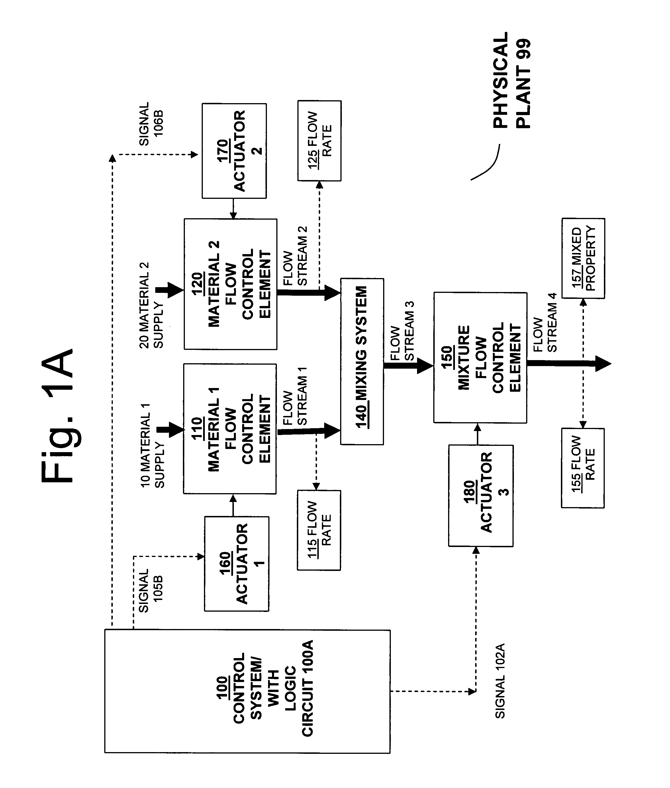
Systems for controlling the in-feed and discharge rates of materials flowing into and out of a mixing process where one priority is to achieve a target mixture flow rate from the mixing process and another priority can be to achieve a target value for a mixture property. Actuators can be operated to control material in-feed rates, the mixture composition, and discharge rate, and can maintain a hold-up of the mixture in the mixing process. A total flow rate controller provides a control signal to a controller acting on the discharge rate and a controller acting on the in-feed rates. The mixture discharge flow rate can be automatically reduced from its desired target when the commanded rate of at least one of the materials exceeds its available supply rate as inferred from an inability to maintain the targeted value for the mixture property.

Description

CROSS-REFERENCE TO RELATED APPLICATIONS[0001]This application claims priority from U.S. Provisional Patent Application 60 / 879,746 filed on Jan. 10, 2007, entitled “Methods and Systems for Self-Balancing Control of Mixing and Pumping”, to Jason D. Dykstra, which is herein incorporated by reference in its entirety.[0002]The following application filed concurrently herewith is not necessarily related to the present application, but is incorporated by reference herein in its entirety: “Methods for Self-Balancing Control of Mixing and Pumping”, U.S. patent application Ser. No. ______, filed simultaneously with the effective filing date of the present application, Attorney Docket Number HES-2006-IP-022199U1).[0003]The following applications are incorporated by reference herein in their entirety: “Methods of Determining a Volumetric Ratio of a Material to the Total Materials in a Mixing Vessel”, U.S. patent application Ser. No. 11 / 323,831, to Jason D. Dykstra and Justin A. Borgstadt, filed...

Claims


Application Information

Patent Timeline
IPC IPC(8): B28C7/04G05D11/02G05D9/00
CPCB01F15/00207B01F15/00233E21B33/14E21B21/062B01F15/00285G05D11/135B01F35/2134B01F35/213B01F35/2202
Inventor DYKSTRA, JASON D.
Owner HALLIBURTON ENERGY SERVICES INC
Learn More