
Integrated photovoltaic modular panel for a curtain wall glass

a photovoltaic modular panel and curtain wall technology, applied in the direction of walls, sustainable buildings, power plants, etc., can solve the problems of increasing the number of photovoltaic panels used in the curtain wall, increasing the number of photovoltaic panels, and complicated assembly process, etc., to achieve the effect of convenient modification

Active Publication Date: 2008-07-10
LI YI
View PDF4 Cites 46 Cited by
  • Summary
  • Abstract
  • Description
  • Claims
  • Application Information

AI Technical Summary

Benefits of technology

[0008]One object of the present invention is to provide a standardized connector on the photovoltaic panel such that the connector is an independent device and can quickly connect with various electrodes in different ways.
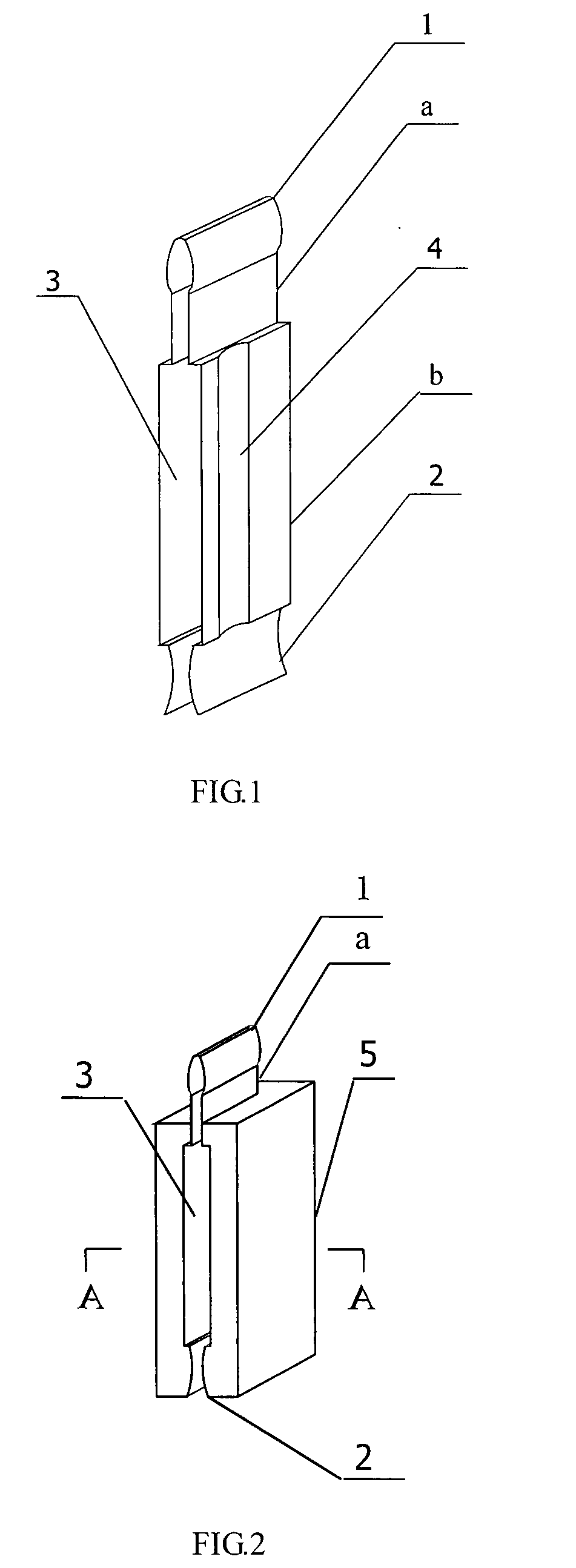
[0011]The internal electrodes of the photovoltaic units are composed of the positive electrode and the negative electrode of at least one solar cell. The connector is a metal piece of stamping or casting, which has a plug and a socket on both ends, an electrode plug-in socket at the waist. The plug is a long spindle and the socket on the bottom is a slot with biconcave section being flexible, by which the plug is convenient to plug into or unplug from said socket, having excellent electrical contact for tight fit. The connector may have a plane symmetry structure.
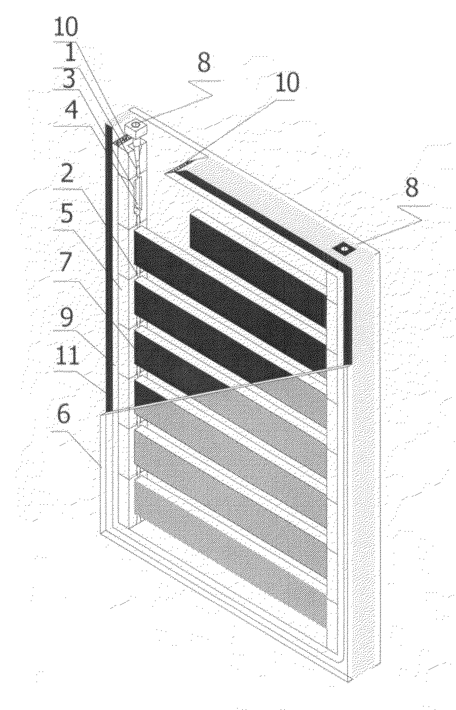
[0014]The invention standardizes the photovoltaic units and modularizes the photovoltaic panels. With a standard plug, the photovoltaic units can be integrated together in various ways. The photovoltaic panel main body is easily be modified according to the field applications. The assembly process of a photovoltaic panel main body by using prepared photovoltaic units becomes very easy and quick. And the photovoltaic panel main body is suit for mass production. Even at the construction site, the photovoltaic panel main body can easily combine with different kinds of glass, forming different kinds of photovoltaic curtain wall glass.

Problems solved by technology

But one issue has been brought as more photovoltaic panels are used in curtain wall glass.
That is, the assembly process can became very complicated and time consuming for the large number of electrodes.
The inner structure of the curtain wall glass may be changed and it requires a large space for transporting.
In addition, the maintenance is quite difficult, for example, the whole frame needs to be dismantled in order to replace a broken solar cell.

Method used


Image

  • Integrated photovoltaic modular panel for a curtain wall glass
  • Integrated photovoltaic modular panel for a curtain wall glass
  • Integrated photovoltaic modular panel for a curtain wall glass

Examples


first embodiment

[0038]The first embodiment is a photovoltaic hollow curtain wall glass. A photovoltaic unit is formed when the solar cell strip's two ends, i.e., a positive electrode and a negative electrode, are respectively connected with a connector with a slantwise electrode plug-in socket 3′ as shown in FIG. 3 and FIG. 4. Multiple photovoltaic units, equipped with crust 5′ around the connector, composes a photovoltaic panel main body through inserting the plug 1′ into the socket 2′ just like stacking building blocks. The internal electrodes of the photovoltaic panel main body are formed with a positive electrode bar and a negative electrode bar respectively parallel connected. The left frame and the right frame of the photovoltaic panel main body are formed by stacking together multiple crusts 5′. The photovoltaic units in the photovoltaic panel main body are arranged with intervals for light transmitting. The photovoltaic panel main body can be directly installed in the inner frame of a hollo...

second embodiment

[0040]The second embodiment is a stand-alone electricity supply system. Photovoltaic arrays comprising multiple integrated photovoltaic panels as mentioned above are parts of a stand-alone electricity supply system or a grid-connected electricity generation network. Referring to FIG. 8, A stand-alone electricity supply system generally has an integrated photovoltaic panel 35, a charge controller 40, an inverter 25 and a battery 30. When the value of the voltage of the output power produced by the integrated photovoltaic panel 35 reaches a predetermined level, through the charger controller 40 the electrical power can be stored in a battery 30 of 12 v, 24 v or 48 v. And then the inverter 25 converts direct current with low voltage to alternating current with 110 v or 220 v, providing a load 20 with steady and secure electrical power.

third embodiment

[0041]The third embodiment is a photovoltaic panel main body integrated with low-emissivity coated glass (low-E glass) or low-iron toughened texture glass (white glass). The photovoltaic panel main body as mentioned above is installed in the middle of low-E glass or white glass. The internal electrodes are fixed and insulated with the inner frame of the glass by coating glue on the surface of the frame. To ensure satisfactory sealing, seal glue is placed between the surface of the photovoltaic panel main body and exterior glass. The internal electrodes are connected with the exterior electrodes. And the exterior electrodes are exposed to the air. So the frame of the photovoltaic panel main body is concealed in the glass.


PUM


Abstract

An integrated photovoltaic modular panel for a curtain wall glass is used for the field of building integrated photovoltaic. The invention provides the standardized photovoltaic units, so that the electrodes in a photovoltaic panel main body can be internally parallel connected. The connector may be a metal piece of stamping or casting, which has a plug 1 and a socket 2 on both ends, a waist b in the middle, an inward concave straight strip 4 on both sides of the waist, an electrode plug-in socket 3 in the waist for firmly clamping solar cell, a plastic injection molding crust 5 for fixing and securing the connector, forming a module. It can combine with different kinds of glass, forming different kinds of photovoltaic curtain wall glass. The solar cell here may be an amorphous silicon solar cell.

Description

BACKGROUND OF THE INVENTION[0001]1. Field of the Invention[0002]The present invention relates to an integrated photovoltaic modular panel for a curtain wall glass, and in particular, to a photovoltaic panel with amorphous silicon thin film solar cells, concerning with the field of building integrated photovoltaic.[0003]2. Description of the Related Art[0004]Currently, solar cells are connected together by conductive wires and formed a panel with hollow glass or laminated glass. Positive electrodes or negative electrodes on every solar cell of photovoltaic panel are connected in series or parallel. The internal wires are soldered together with an external lead. So the more solar cells to be parallel connected the lower mounting-efficiency is. Regardless of types of electricity supply systems, e.g., a stand-alone system or a networked system, the core of a PV system is a photovoltaic panel made of solar cells. A thin film solar cell does not use the silicon wafer. Instead, it uses a n...

Claims


Application Information

Patent Timeline
Patent Type & Authority Applications(United States)
IPC IPC(8): H01L31/042E04B2/88H01L31/048H01L31/05
CPCE04B2/88H01L31/042H01L31/0508Y02E10/50H01L31/0488Y02B10/12Y02A30/60Y02B10/10
Inventor LI, YI
Owner LI YI
Learn More