
Refrigerated cabinet and cooling module for same

a technology of refrigeration cabinet and cooling module, which is applied in the direction of gas/liquid distribution and storage, applications, lighting and heating apparatus, etc., can solve the problems of insufficient amount of cool generated through the peltier effect of currently available units, significant lifespan, and difficulty in necessary repair or maintenance, so as to reduce the space requirement, the effect of minimizing the height of the casing and full width

Inactive Publication Date: 2008-07-10
LILKE HARVEY D
View PDF12 Cites 40 Cited by
  • Summary
  • Abstract
  • Description
  • Claims
  • Application Information

AI Technical Summary

Benefits of technology

[0013]The module allows any cabinet to be cooled simply by placing the module at the top or bottom of the cabinet's interior for exposure of the air therein to the cold end of the cooling system. The module can therefore be used to replace the cooling system of a previously refrigerated cabinet or provide cooling where there was none previously provided. The module can be transported from one place to another for use with different cabinets.
[0020]Preferably the cold end is disposed within the casing and openings are provided in the one of the top and bottom walls at which the cold end is exposed to the exterior of the housing. While the cold end and the cool transmitting member could be supported atop the casing for direct exposure to the surrounding air, positioning them within the casing protects the components from accidental damage and maintains compact and ease of placement in various cabinet designs.
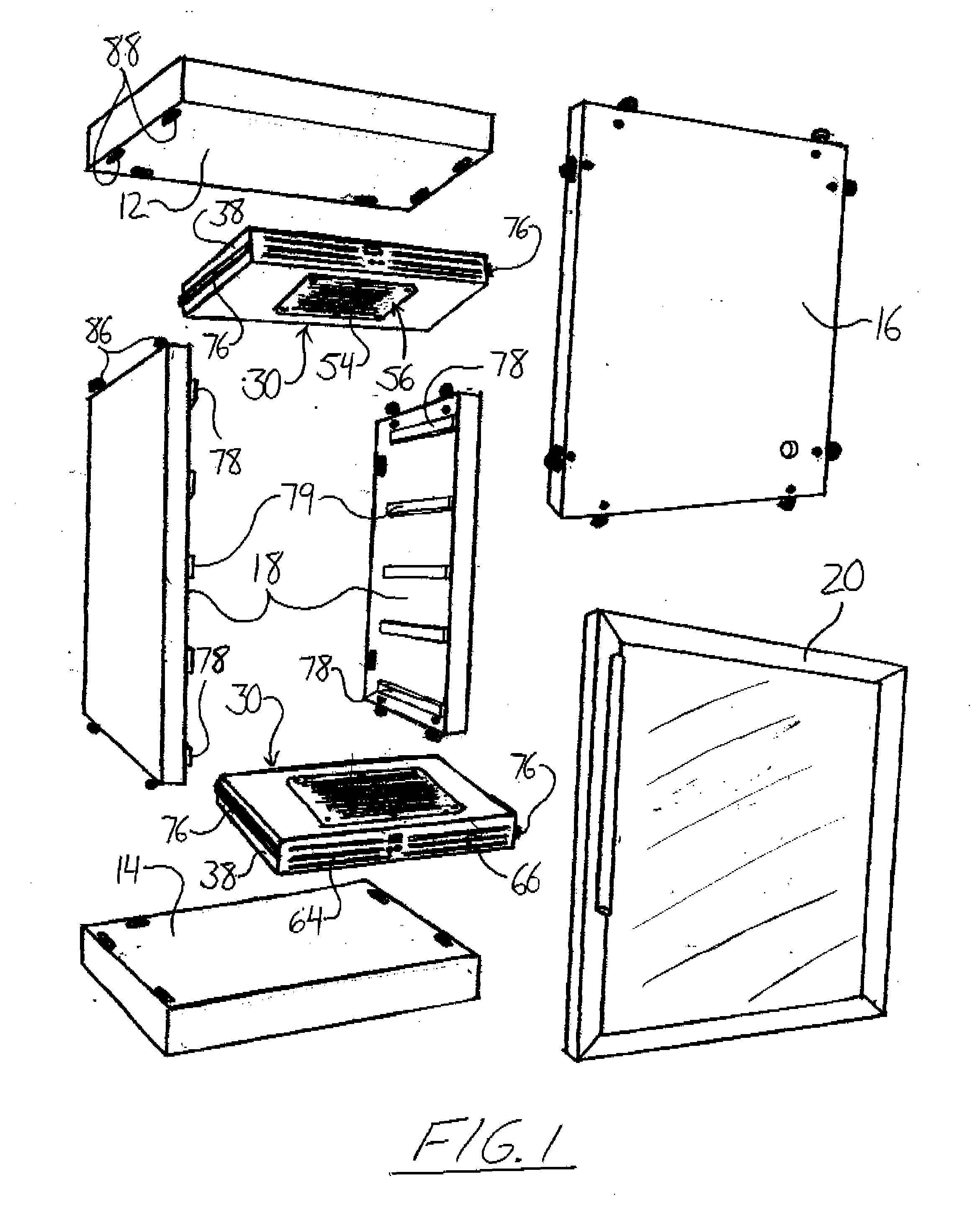
[0023]Preferably the cooling module is provided in combination with a cabinet, the cabinet being formed of insulated panels including a top wall, a bottom wall, side walls and a rear wall connected to define an open front and a front door connected to the cabinet and movable between an open position exposing the open front and a closed position at least partly covering the open front, wherein the side walls of the casing having slide members supported thereon at the exterior of the casing for engaging cooperating slide members on the inside surface of the side walls allowing sliding movement of the casing into the cabinet through the open front face to allow cooling to be provided within the cabinet by the cold end of the cooling system.
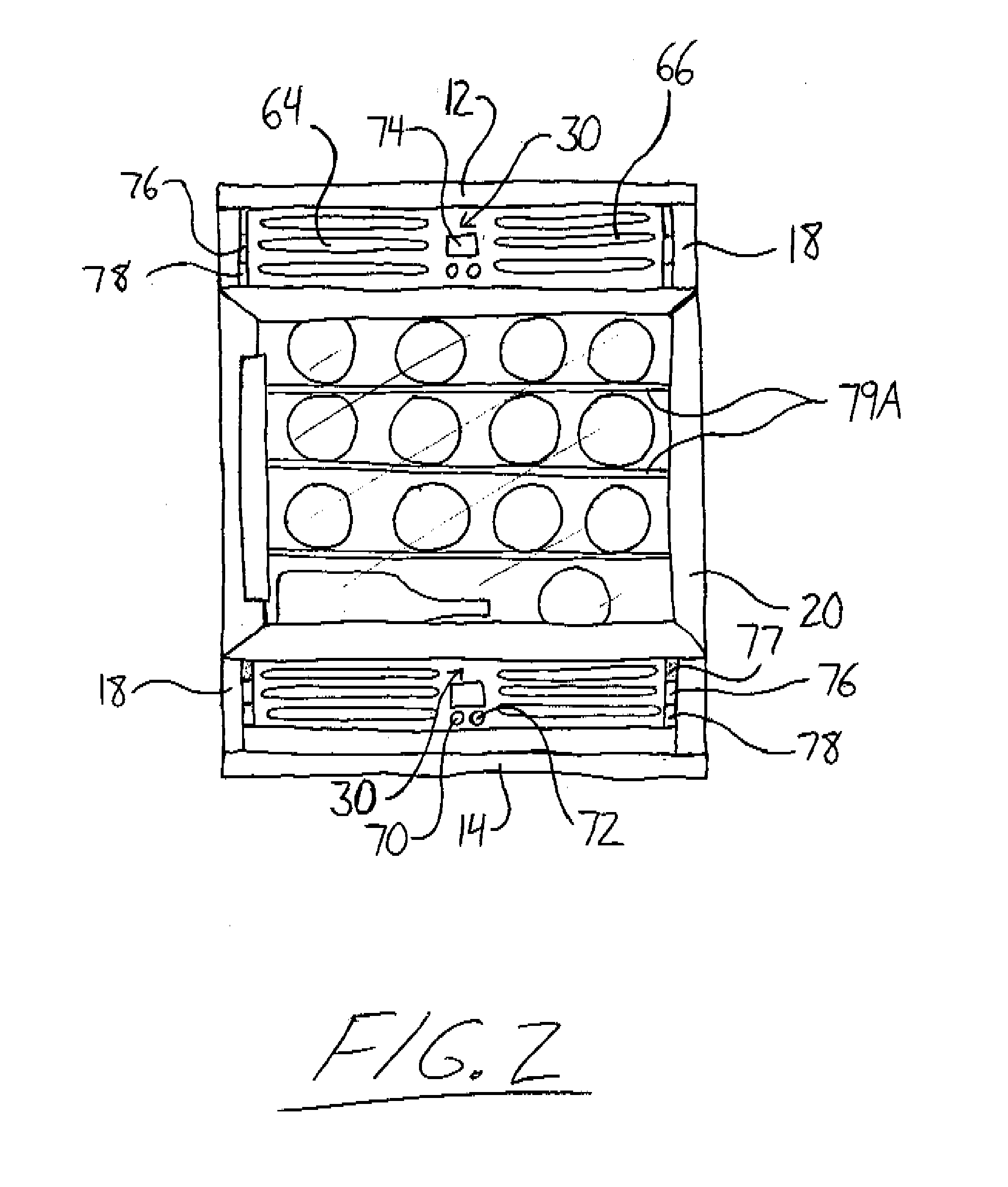
[0024]The front door may be dimensioned to define a slot shaped opening portion of the open front below the front face of the door and the casing is located at the bottom of the cabinet with the cold end exposed to the exterior of the casing at the top wall thereof and with the discharge openings aligned with the opening portion. Alternatively, the front door may be dimensioned to define a slot shaped opening portion of the open front above the front face of the door and the casing is located at the top of the cabinet with the cold end exposed to the exterior of the housing at the bottom wall thereof and with the discharge openings aligned with the opening portion. As a further alternative, the door may be arranged to cover the whole of the front opening and to include an opening which aligns with the front openings in the casing to allow the heated air to escape. Having the module arranged to discharge hot air from the front of the cabinet allows the cabinet to be backed against a wall or other surface or into a corner without worrying about blocking the exhaust. This reduces the space requirement as it is not necessary to leave space between the cabinet and the wall.
[0025]Preferably the casing spans the full width between the side walls of the cabinet. The intention is that the casing is shaped and arranged in conjunction with particular components of the cooling system so that the full width is effectively utilized while allowing the height of the casing to be minimized. Different casings can be manufactured to cooperate with different size or different width cabinets. However the width of the casing may be less than the full width and supports or slide members can be provided which take up some of the width, allowing a narrower casing to be used with a wider cabinet. The wide casing allows a full width of the front face to be used as a heated air release area.
[0026]Preferably the side walls of the cabinet have rails attached thereto on which the casing slides. These are preferably pre-applied in a kit of parts for assembly into the cabinet. However slots in the side walls can also be used as a simple support for the casing.

Problems solved by technology

Thermoelectric cooling systems can be used in different thermoelectric orientations as no refrigeration fluids are utilized and have significant lifespans due to a lack of moving parts.
The amount of cool generated through the Peltier effect in currently available units is typically insufficient for many applications such as freezers or air conditioning but can be, and is widely, used in chillers for beverages such as wine coolers.
This may make any necessary repair or maintenance difficult due to accessibility issues.

Method used


Image

  • Refrigerated cabinet and cooling module for same
  • Refrigerated cabinet and cooling module for same
  • Refrigerated cabinet and cooling module for same

Examples


Embodiment Construction

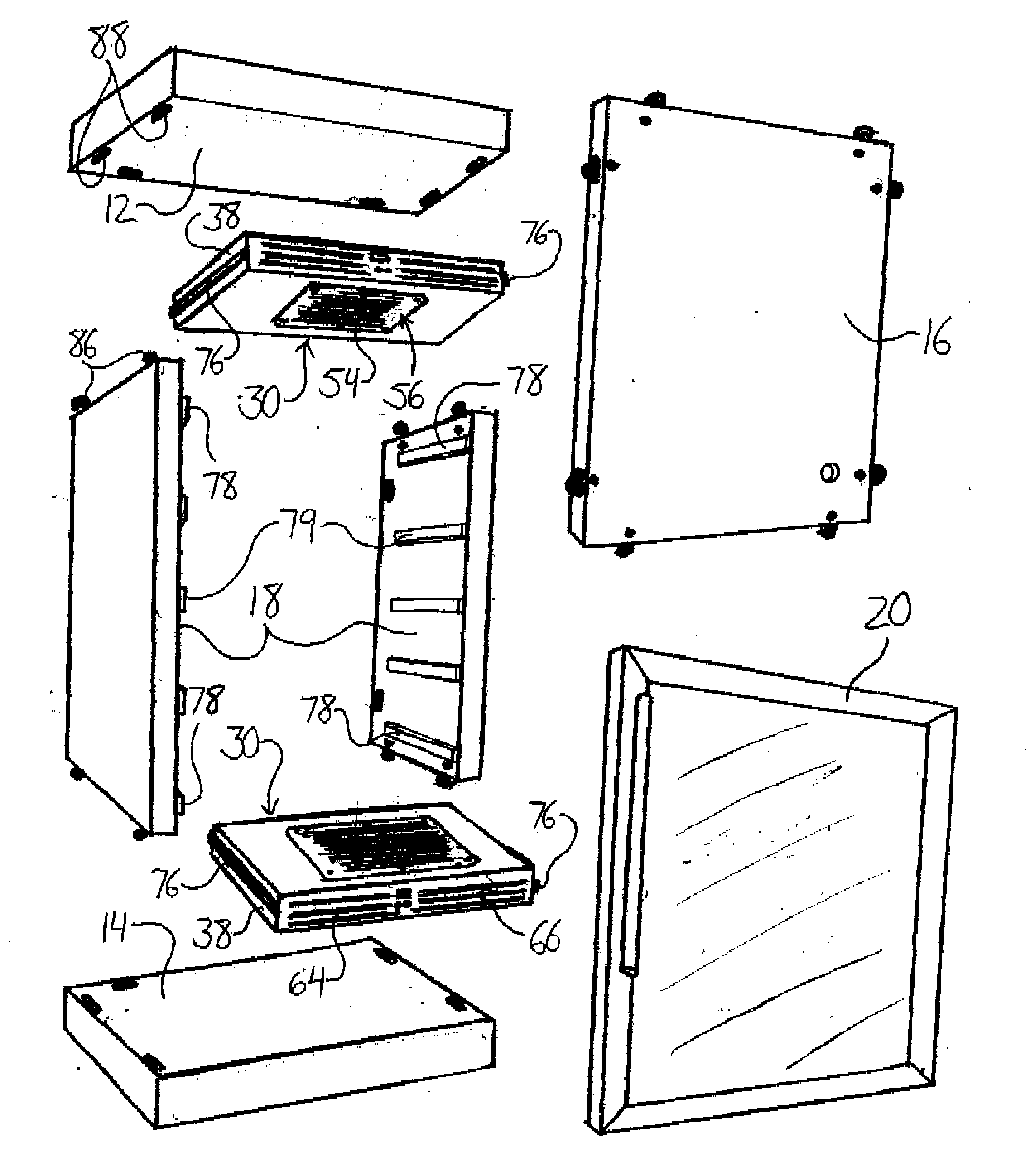
[0054]FIGS. 1 and 2 show a refrigerated cabinet 10 that makes use of slide-in cooling modules. The cabinet 10 features insulated panels forming a top wall 12, bottom wall 14, rear wall 16 and two sides walls 18 assembled and interconnected to define an interior having an open front end. The cooling modules 30 are arranged to slide into the cabinet from the open front end 10 at the top and bottom of the interior. The modules adjacent the top and bottom walls of the cabinet provide cooling from their bottom and top surfaces respectively to cool the air between the modules within the cabinet interior. A door 20 is pivotally mounted on the panels at the open front end to enable opening and closing of the cabinet by pivoting the door between open and closed positions in which the open front end is at least partially unobstructed and fully covered respectively. The cooling modules 30 are easy to install, easy to remove and allow the conversion of essentially any cabinet-like structure int...


PUM


Abstract

A cooling module mountable within a cabinet to provide cooling of the interior thereof has a cold end of its cooling system exposed to an exterior of the module at a top or bottom wall of its casing. A fan is mounted within the cabinet to discharge warm air heated by a hot end of the cooling system through discharge openings provided in an end panel of the casing. Cabinet walls may be provided in the form of one or more laminate sheets having an insulating layer and an exterior cladding. The one or more sheets may be bent or assembled as needed to form the cabinet structure. Shipping the cabinet to an end user or intermediary in flat panel form reduces the necessary volume of packaging to ease handling and reduce shipping costs.

Description

[0001]The present invention relates to a refrigerated cabinet primarily, but not exclusively, designed for cooling wine bottles and a cooling apparatus for cooling the interior of any cabinet having walls that may be, if not already, equipped with insulation.BACKGROUND OF THE INVENTION[0002]One example of a refrigerated cabinet is disclosed in my prior PCT Published application PCT / CA2005 / 044060 published 19 May 2005 which discloses a modular system of providing a cooling cabinet primarily for wine bottles where the cabinet and the storage capacity provided thereby can be increased by adding further modules to the construction. In this device the cooling is provided in one embodiment by a conventional cooling system located in the cabinet itself or in a second arrangement, the cooling is provided as separate cooling elements each within a respective one of a plurality of cooling racks located in the cabinet.[0003]In U.S. Pat. No. 6,715,298 (Guo) assigned to Hebei Energy Conservation...

Claims


Application Information

Patent Timeline
IPC IPC(8): F25B21/02
CPCF25B21/02F25B2321/021F25B2321/023F25B2321/0251F25D23/063F25D31/007F25D2400/32F25D2317/0655F25D2317/0661F25D2317/0665F25D2317/0683F25D2323/061F25D2317/0651
Inventor LILKE, HARVEY D.
Owner LILKE HARVEY D
Learn More