Signal processing device and audio playback device having the same
- Summary
- Abstract
- Description
- Claims
- Application Information
AI Technical Summary
Benefits of technology
Problems solved by technology
Method used
Image


Examples
Embodiment Construction
[0017]Hereinafter, embodiments of the invention will be described with reference to the accompanying drawings. The following description of the preferred embodiments is essentially by way of example only and is not intended to limit applications or usages of the invention.
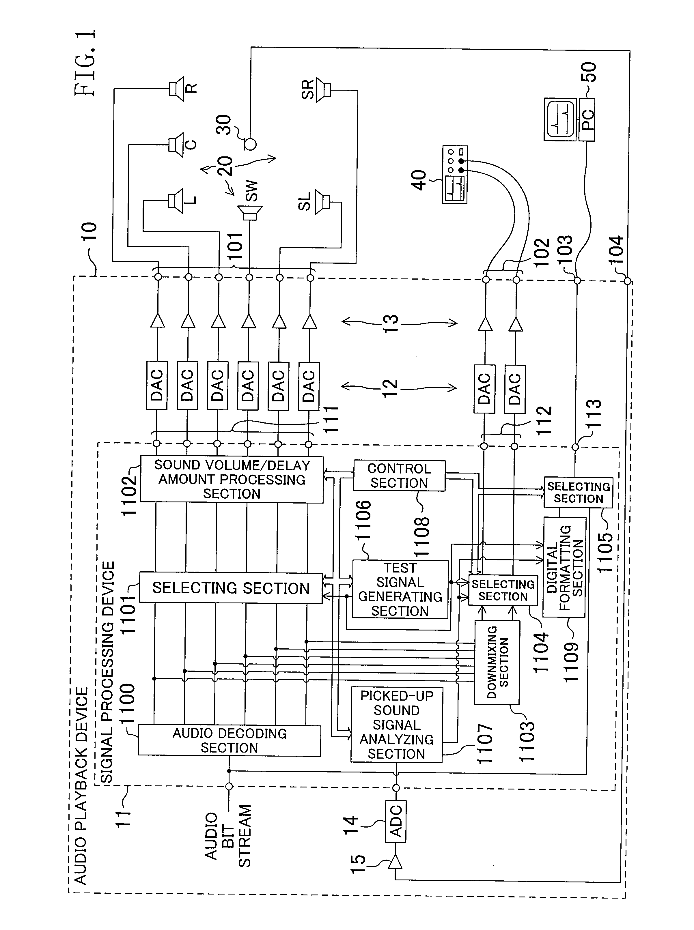
[0018]FIG. 1 shows the structure of a 5.1 channel audio system including a signal processing device and an audio playback device according to the invention. An audio playback device 10 includes a signal processing device 11, a digital-to-analog (D-A) converter (DAC) group 12, an amplifier group 13, an analog-to-digital (A-D) converter (ADC) 14, and an amplifier 15. A 5.1 channel digital audio signal and a 2 channel digital audio signal are output from the signal processing device 11, D-A converted by the DAC group 12, and amplified by the amplifier group 13. The resultant analog signals are output from a speaker output terminal 101 and a headphone output terminal 102, respectively. An audio bit stream is output fro...
PUM
 Abstract
Description
Claims
Application Information
 - R&D
- Intellectual Property
- Life Sciences
- Materials
- Tech Scout
- Unparalleled Data Quality
- Higher Quality Content
- 60% Fewer Hallucinations
Browse by: Latest US Patents, China's latest patents, Technical Efficacy Thesaurus, Application Domain, Technology Topic, Popular Technical Reports.
© 2025 PatSnap. All rights reserved.Legal|Privacy policy|Modern Slavery Act Transparency Statement|Sitemap|About US| Contact US: help@patsnap.com