
High Voltage X-Ray Generator and Related Oil Well Formation Analysis Apparatus and Method

a technology of high-voltage x-ray generator and oil well, which is applied in the direction of x-ray tubes, instruments, borehole/well accessories, etc., can solve the problems of high operating requirements, high liability of radioactive sources, and the current fluctuation of most electrical photon generators

Active Publication Date: 2008-07-03
SCHLUMBERGER TECH CORP
View PDF7 Cites 20 Cited by
  • Summary
  • Abstract
  • Description
  • Claims
  • Application Information

AI Technical Summary

Benefits of technology

The present invention is an apparatus and method for determining properties of the formation surrounding a borehole in a well services environment. It uses a high voltage x-ray generator with a carefully controlled acceleration voltage and beam current to provide a reliable measure of the characteristics of a formation surrounding a borehole. The apparatus includes an x-ray generator, an x-ray detector, and a reference detector. The x-ray generator provides radiation with energy greater than or equal to 250 keV and operates at temperatures greater than or equal to 125° C. The radiation output by the x-ray generator is filtered to produce a radiation spectrum with a high energy region and a low energy region, which is used to control the acceleration voltage and beam current of the x-ray generator. The invention can be used in a well services environment to determine the density and Pe of the formation surrounding a borehole. It provides a reliable measure of the characteristics of a formation surrounding a borehole.

Problems solved by technology

While this radioisotope source type of system can provide an accurate result, there are drawbacks to the use of a chemical source such as 137Cs in measurements in the field.
Any radioactive source carries high liability and strict operating requirements.
An electrical photon (radiation) generator would alleviate some of these concerns, but most electrical photon generators (such as x-ray generators) are subject to issues such as voltage and beam current fluctuation.
If a tube operating below 250 kV is used, the electron current required will typically be too great to produce density measurements with reasonable efficiency.

Method used


Image

  • High Voltage X-Ray Generator and Related Oil Well Formation Analysis Apparatus and Method
  • High Voltage X-Ray Generator and Related Oil Well Formation Analysis Apparatus and Method
  • High Voltage X-Ray Generator and Related Oil Well Formation Analysis Apparatus and Method

Examples


Embodiment Construction

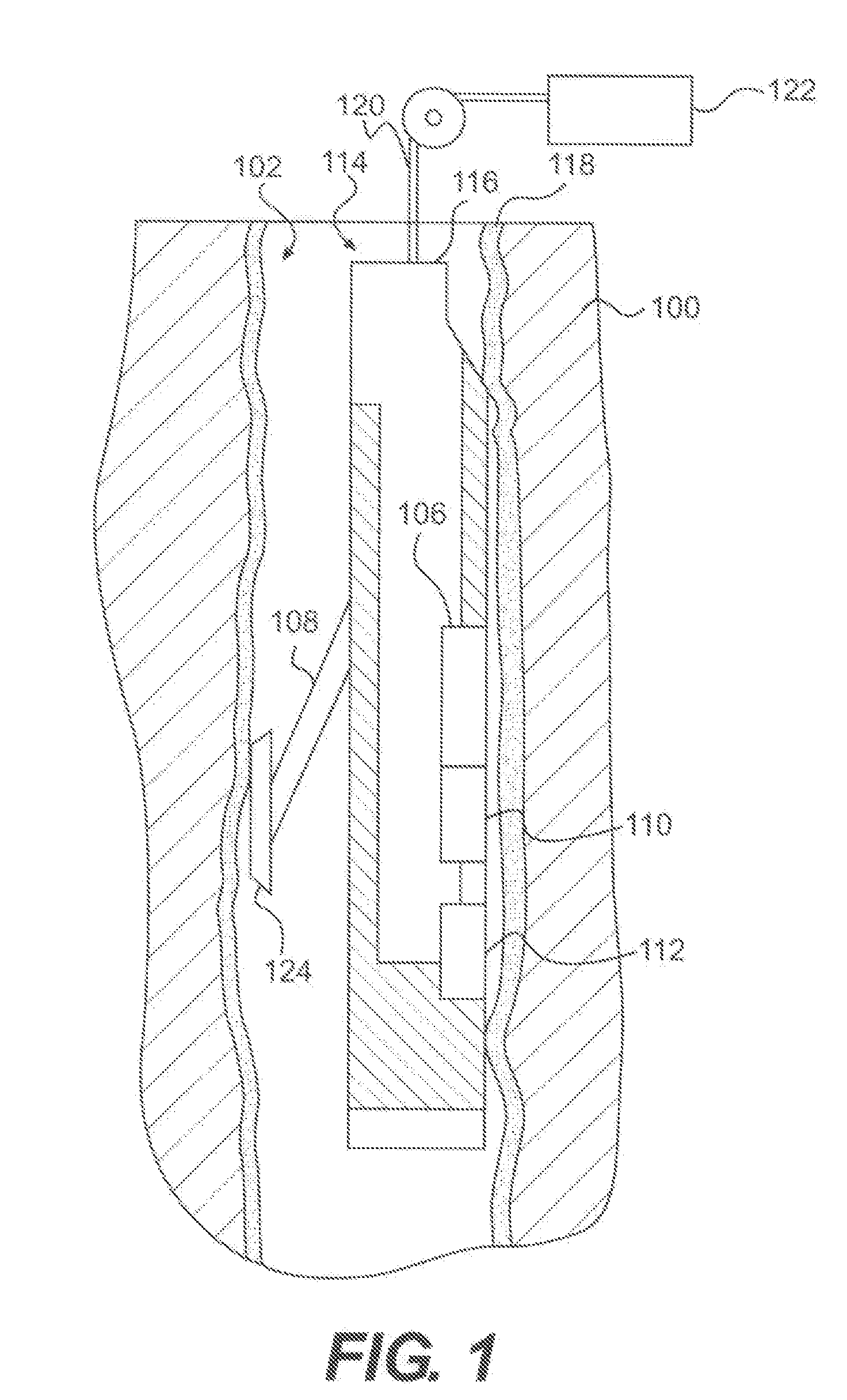
[0029]Referring now to the drawings and particularly to FIG. 1 wherein like numerals indicate like parts, there is shown a schematic illustration of an operational context of the instant invention. This figure shows one example of an application of the invention for determining the density and other properties of the formation surrounding a borehole 102. As described above, the tool 114 is positioned downhole to determine properties of formation 100 using input radiation that is subsequently detected.

[0030]In the embodiment of FIG. 1, tool 114 comprises sonde body 116 that houses all components that are lowered into borehole 102. X-ray generator 112 introduces radiation into formation 100. This radiation is to some extent scattered from different depths in the formation 100 and the resultant radiation signal is detected at short spaced detector 110 and long spaced detector 106.

[0031]During the drilling process, the borehole may be filled with drilling mud. The liquid portion of the ...


PUM


Abstract

An apparatus and method for determining the density and other properties of a formation surrounding a borehole using a high voltage x-ray generator. One embodiment comprises a stable compact x-ray generator capable of providing radiation with energy of 260 keV and higher while operating at temperatures equal to or greater than 125° C. In another embodiment, radiation is passed from an x-ray generator into the formation; reflected radiation is detected by a short spaced radiation detector and a long spaced radiation detector. The output of these detectors is then used to determine the density of the formation. In one embodiment, a reference radiation detector monitors a filtered radiation signal. The output of this detector is used to control at least one of the acceleration voltage and beam current of the x-ray generator.

Description

BACKGROUND[0001]This disclosure relates to an apparatus and method for evaluating a formation surrounding a borehole using an x-ray generator. More specifically, this disclosure relates to a system for using x-rays to determine the density of the formation. The measurements are taken using a downhole tool comprising an x-ray generator and a plurality of radiation detectors. The x-ray generator is capable of emitting radiation with high enough energy to pass into the formation and allow for substantive analysis of radiation reflected and received at the plurality of radiation detectors. In one embodiment, a reference radiation detector is used to control the acceleration voltage and beam current of the x-ray generator.[0002]Well logging instruments utilizing gamma ray sources and gamma detectors for obtaining indications of the density and photoelectric effect (Pe) of the formation surrounding a borehole are known. A typical device comprises a long sonde body containing a gamma ray r...

Claims


Application Information

Patent Timeline
Patent Type & Authority Applications(United States)
IPC IPC(8): G01B15/02H01J35/00
CPCH01J35/06H01J35/14H01J2235/0233H05G1/10H01J2235/163H05G1/02H01J2235/06G01V5/125H01J35/02E21B49/00G01V5/08
Inventor WRAIGHT, PETERBECKER, ARTHUR J.GROVES, JOEL L.STOLLER, CHRISTIAN
Owner SCHLUMBERGER TECH CORP
Learn More