
Voice control welding/cutting helmet functions and settings

Active Publication Date: 2008-07-03
ILLINOIS TOOL WORKS INC
View PDF27 Cites 148 Cited by
  • Summary
  • Abstract
  • Description
  • Claims
  • Application Information

AI Technical Summary

Benefits of technology

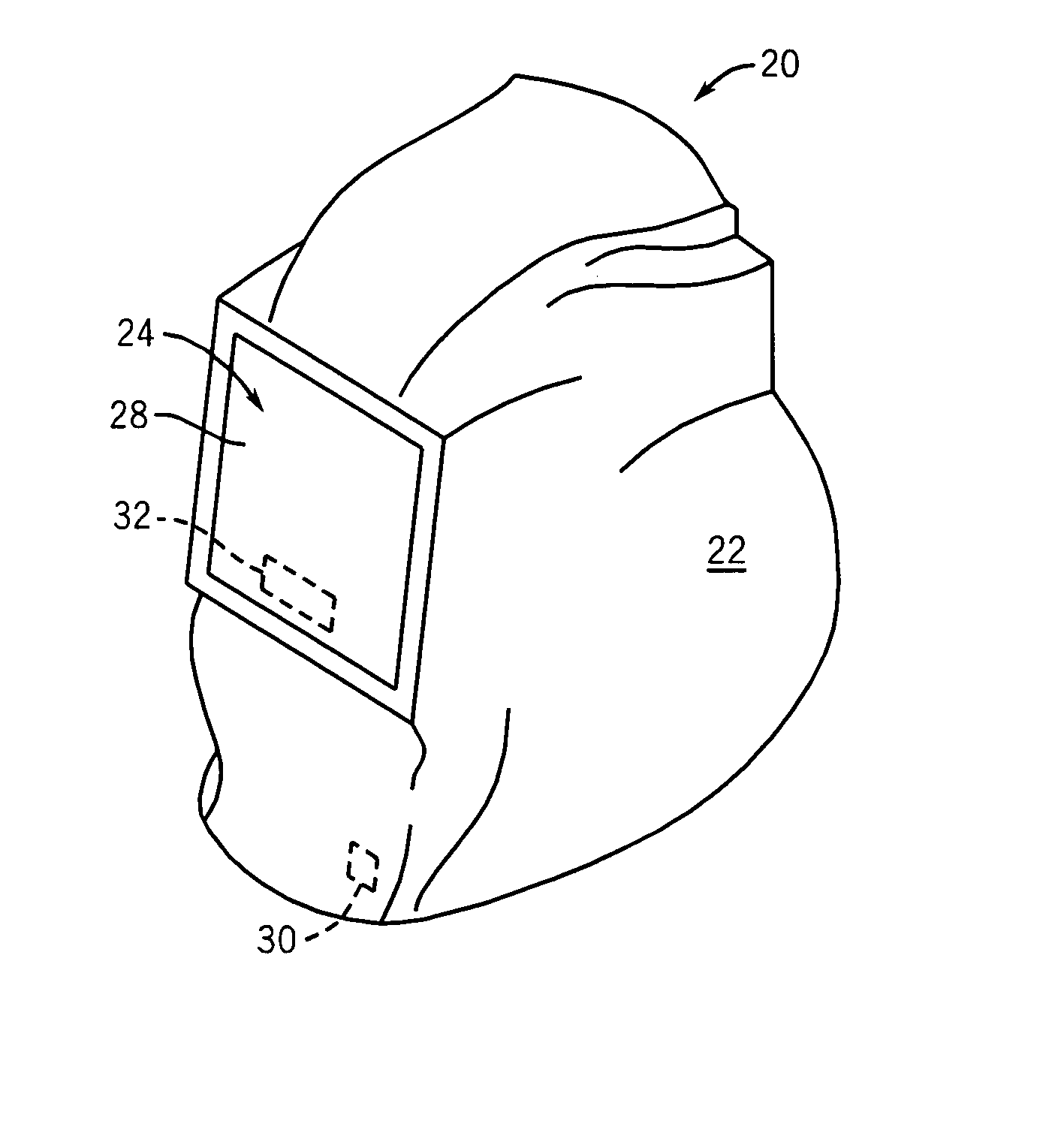
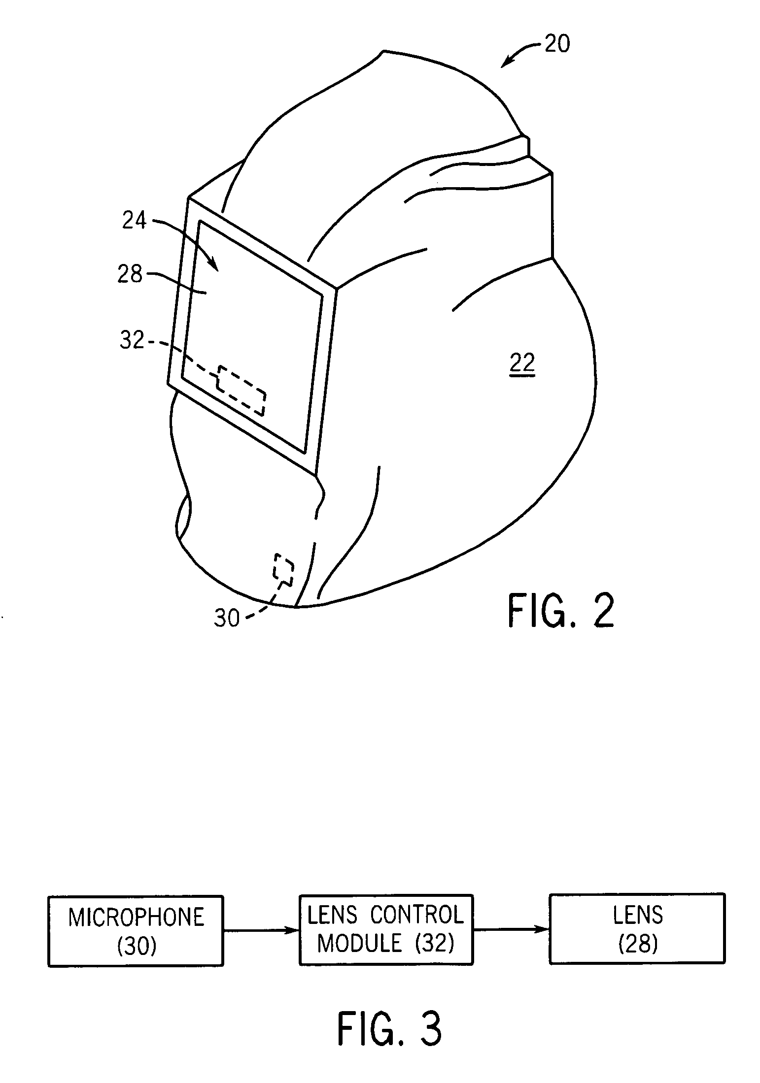
[0004]In accordance with one aspect of the present invention, a welding helmet includes a helmet shell; an electronically controllable lens mounted to the shell; a microphone configured to receive an audible input and to generate a signal in response to the audible input received. An electronic control module is coupled to the lens and to the microphone and configured to control the electronically controllable lens based upon the signal.
[0005]In accordance wi

Problems solved by technology

In these instances, it may be time consuming and laborsome for the welder to manually adjust the settings of the lens.

Method used


Image

  • Voice control welding/cutting helmet functions and settings
  • Voice control welding/cutting helmet functions and settings
  • Voice control welding/cutting helmet functions and settings

Examples


Embodiment Construction

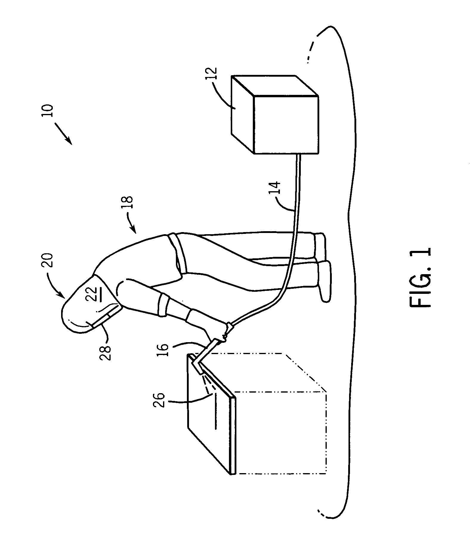
[0023]The present invention may have uses in a variety of welding applications. For example, FIG. 1 illustrates an arc welding system 10. As depicted, the arc welding system 10 may include a power supply 12 that generates and supplies a current to an electrode 16 via a conduit 14. In the arc welding system 10, a direct current (DC) or alternating current (AC) may be used along with a consumable or non-consumable electrode 16 to deliver the current to the point of welding. In such a welding system 10, an operator 18 may control the location and operation of the electrode 16 by positioning the electrode 16 and triggering the starting and stopping of the current flow.

[0024]In welding operations employing welding system 10 depicted in FIG. 1, welding is generally performed with certain precautions due to the generation of heat, and bright light in visible and non-visible spectra. To avoid overexposure to such light, a helmet assembly 20 is worn by the welding operator 18. The helmet ass...


PUM

PropertyMeasurementUnit
Sensitivityaaaaaaaaaa

Abstract

Provided for is a control system for a welding helmet comprising: an electronically controllable lens configured to be mounted in a welding helmet shell, a microphone configured to receive an audible input and to generate a signal in response to the audible input received and an electronic control module coupled to the lens and to the microphone and configured to control the electronically controllable lens based upon the signal. Also provided for is a welding helmet implementing a control system and a method of manufacturing a welding helmet including a control system.

Description

BACKGROUND[0001]The present invention relates generally to welding helmets and, more particularly, to the control methods by which the user adjusts settings of functions within a welding helmet.[0002]Welding operations are generally performed with certain precautions due to the potential exposure of the welding operator to high heat, flames, weld spatter and ultraviolet light. For example, in arc welding, an arc may provide extremely bright emissions in the weld area that may lead to a condition known as “eye arc” in which ultraviolet light causes the inflammation of the cornea and can burn the retina of the eyes if they are unprotected. To prevent such a condition, goggles and helmets are worn by welders. These helmets generally include a face plate (or lens) that is darkened to prevent or limit exposure to the arc light. In some helmets, the lens is constantly dark with the user flipping down the helmet during welding. In other helmets, the lens may change from a clear state to a ...

Claims


Application Information

Patent Timeline
IPC IPC(8): G02C7/10A61F9/06
CPCY10T29/49A61F9/067
Inventor BECKER, WILLIAM J.BACHMEIR, HANS J.
Owner ILLINOIS TOOL WORKS INC
Learn More