
Array antenna system

a technology of array antennas and antenna systems, applied in the field of array antennas, can solve the problems of increasing interference with other devices, cost and the size of the antenna system, and taking a long time to acquire the optimum tilt angl

Active Publication Date: 2008-07-03
SAMSUNG ELECTRONICS CO LTD
View PDF3 Cites 18 Cited by
  • Summary
  • Abstract
  • Description
  • Claims
  • Application Information

AI Technical Summary

Benefits of technology

[0011]The present invention provides an array antenna system for reducing a time taken to find an optimum tilt angle, providing a high main lobe gain and a low sidelobe level, and achieving a reduction in cost and a decrease in power consumption by virtue of a simplified structure.

Problems solved by technology

This method has a disadvantage in that it takes a long time to acquire an optimum tilt angle.
Additionally, because each antenna element needs to include a separate variable phase shifter, the cost and the size of the antenna system are high, which is problematic.
However, the single variable phase shifter raises the sidelobe level, creating a disadvantage in that interference with other devices is increased.

Method used


Image

  • Array antenna system
  • Array antenna system
  • Array antenna system

Examples


Embodiment Construction

[0033]Certain exemplary embodiments of the present invention will now be described in greater detail with reference to the accompanying drawings.

[0034]In the following description, same drawing reference numerals are used for the same elements even in different drawings. The matters defined in the description, such as the detailed construction and elements, are provided to assist in a comprehensive understanding of the invention. Thus, it is apparent that the present inventive concept can be carried out without those specifically defined matters. Also, well-known functions or constructions are not described in detail since they would obscure the invention with unnecessary detail.

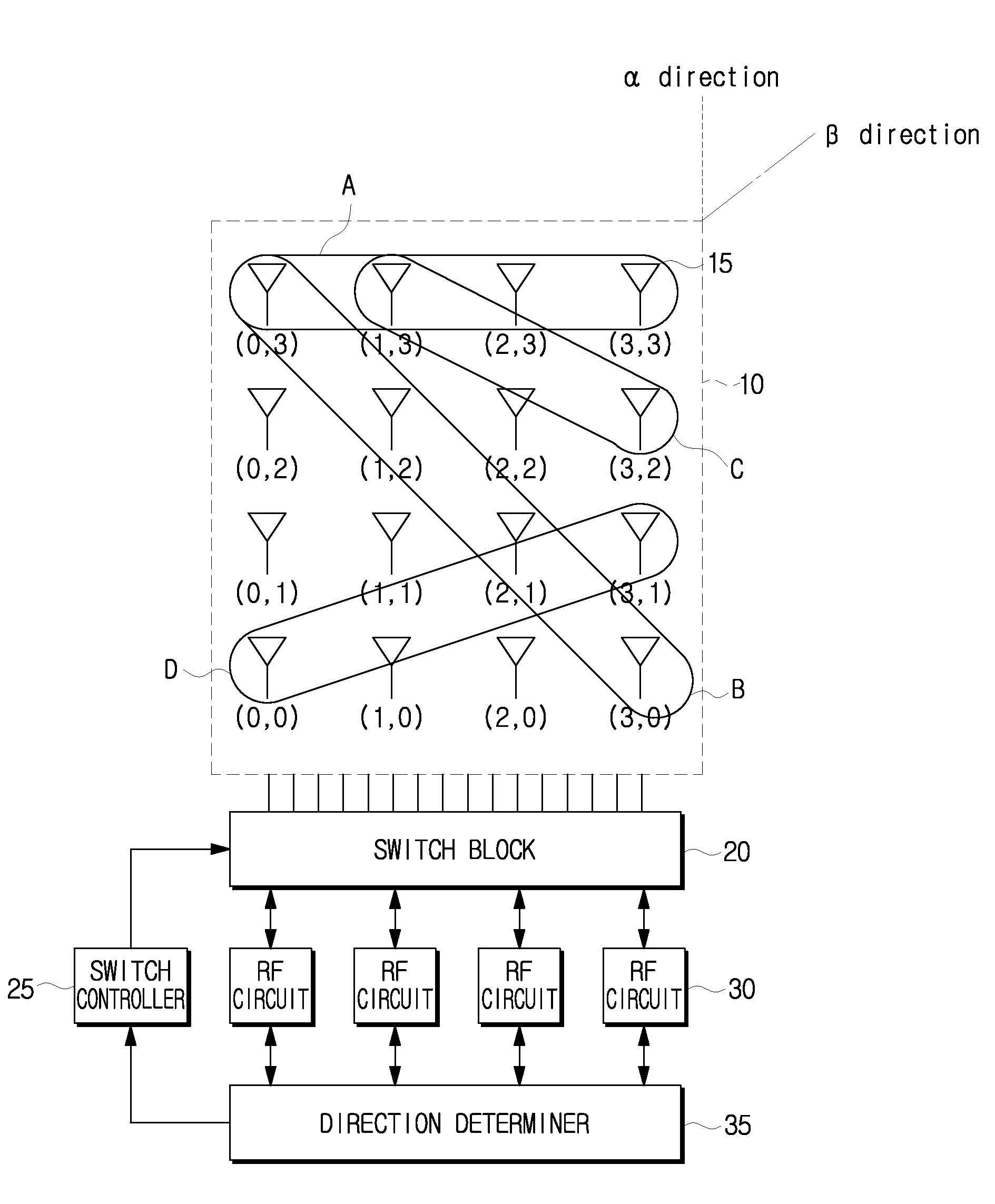
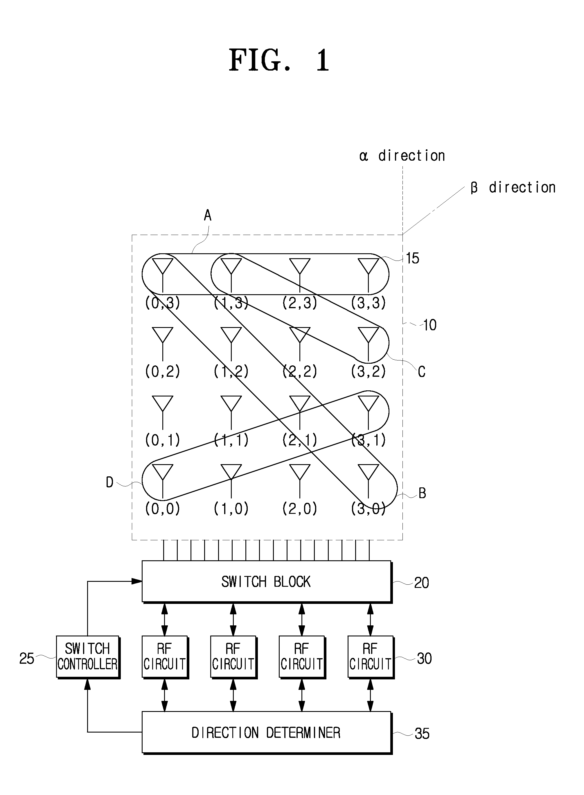
[0035]FIG. 1 is a diagram of an array antenna system according to an exemplary embodiment of the present invention.

[0036]The array antenna system includes an antenna array 10 including a plurality of antenna elements 15, a switch block 20, a switch controller 25, at least one RF circuit 30, and a direction d...


PUM


Abstract

An array antenna system is provided. The array antenna system includes a plurality of antenna elements which are arranged at intervals in rows and in columns; and a control means which selectively operates at least two antenna elements of the plurality of the antenna elements according to a direction of received radio signals.

Description

CROSS-REFERENCE TO RELATED APPLICATIONS[0001]This application claims priority from Korean Patent Application No. 10-2006-0136582, filed on Dec. 28, 2006 in the Korean Intellectual Property Office, the disclosure of which is incorporated herein by reference in its entirety.BACKGROUND OF THE INVENTION[0002]1. Field of the Invention[0003]Systems consistent with the present invention relate to an array antenna and, more particularly, to an array antenna system for rapidly producing a beam patterns in accordance with a communication direction of radio signals.[0004]2. Description of the Related Art[0005]Recently, in the radio communications, a communication scheme is being developed to transmit and receive radio signals over a short range. It is known in the art to employ an array antenna for such communications. Such a communication scheme is often used in millimeter wave communication. However, array antennas, along with their associated techniques, are used in other types of communica...

Claims


Application Information

Patent Timeline
Patent Type & Authority Applications(United States)
IPC IPC(8): H01Q3/00
CPCH01Q3/24H01Q3/28H04B7/0874H04B7/0834H01Q21/061Y02D30/70
Inventor YONG, SU-KHIONGKIM, YOUNG-HWAN
Owner SAMSUNG ELECTRONICS CO LTD
Learn More