
Low voltage ride through system for a variable speed wind turbine having an exciter machine and a power converter not connected to the grid

a low-voltage ride-through system and variable-speed wind turbine technology, which is applied in the direction of machines/engines, mechanical equipment, electric generator control, etc., can solve the problems affecting the performance of the variable-speed wind turbine, and not being able to protect the system. the effect of increasing the dc bus voltag

Inactive Publication Date: 2008-07-03
INGETEAM POWER TECH
View PDF44 Cites 52 Cited by
  • Summary
  • Abstract
  • Description
  • Claims
  • Application Information

AI Technical Summary

Benefits of technology

[0019]Another aspect provides that the exciter machine side converter operates at any time with a stable voltage, so all the power capacity of the converter is kept during voltage disturbances. To the contrary, the majority of recent solutions have a grid side converter having a power capacity that is limited to the grid residual voltage. So, within the present invention the performance of the variable speed wind turbine may be improved considerably during voltage disturbances.

Problems solved by technology

However, this switching disabling is not enough to protect the system because the rotor current flows thorough the converter diodes to the DC Bus circuit, increasing the DC BUS Voltage.
This over voltage could damage the converter components.
However, the growth of wind power generation is forcing the creation of new grid code specifications, so the wind power generation must adapt to these new requirements.
This feature is the source of a very important issue when a transient voltage occurs in the grid.
As will be explained, this grid side converter presents a functional limitation when a fault occurs, because the grid side converter is going to operate with a reduced grid voltage (depending on the grid fault), so its energy evacuation capacity is reduced.
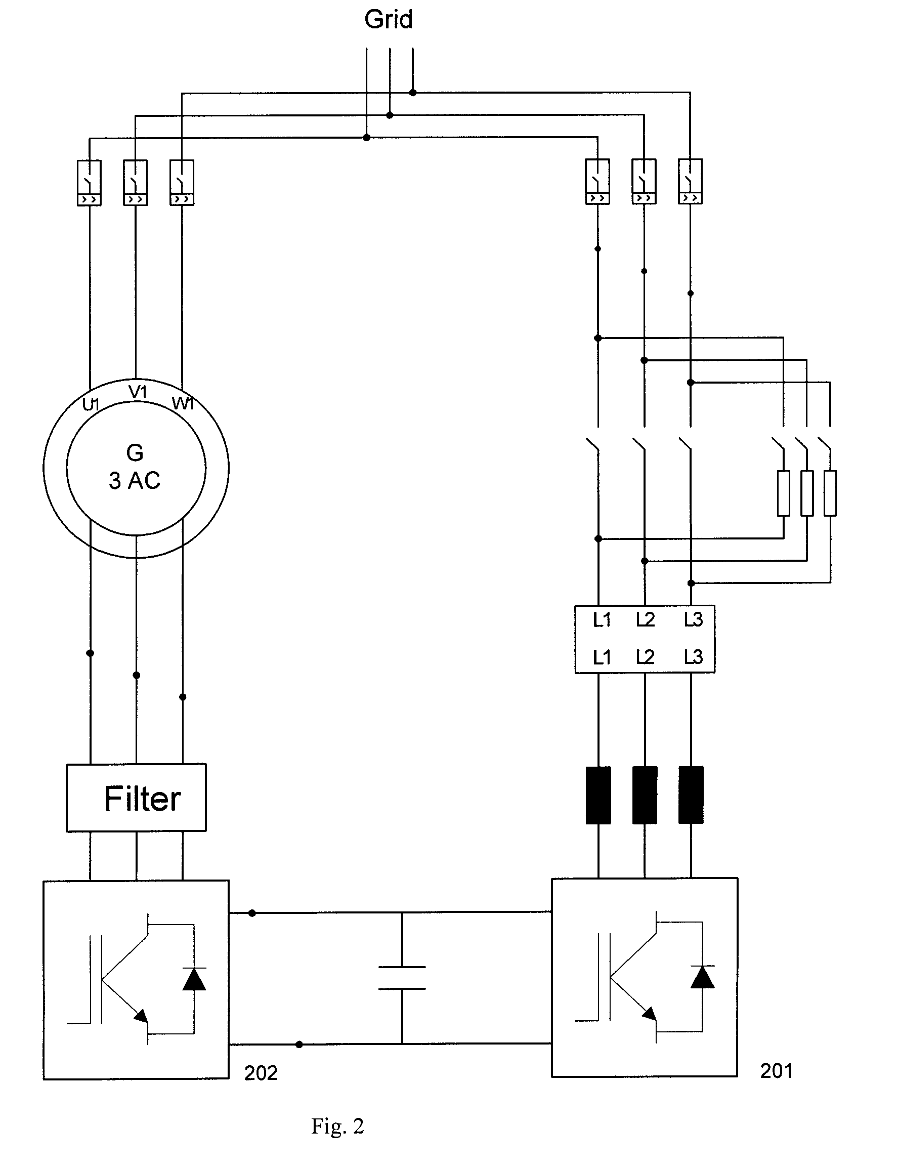
Currently, when a grid fault occurs, the generator demagnetizing energy is sent to the BUS and due to the grid side converter limitation, the BUS voltage rises and could damage converter components.
In these types of solutions, every disturbance or fluctuation occurring in the grid directly affects the grid side converter, so its current limitation implies that the performance of the wind turbine during a grid fault is not completely optimized.

Method used


Image

  • Low voltage ride through system for a variable speed wind turbine having an exciter machine and a power converter not connected to the grid
  • Low voltage ride through system for a variable speed wind turbine having an exciter machine and a power converter not connected to the grid
  • Low voltage ride through system for a variable speed wind turbine having an exciter machine and a power converter not connected to the grid

Examples


Embodiment Construction

[0031]A variable speed wind turbine and its control mode when voltage disturbances occur in the grid are described below. Several drawings will be referenced only as illustration for the better understanding of the description. Furthermore, the same reference numbers will be used along the description referring to the same or like parts.

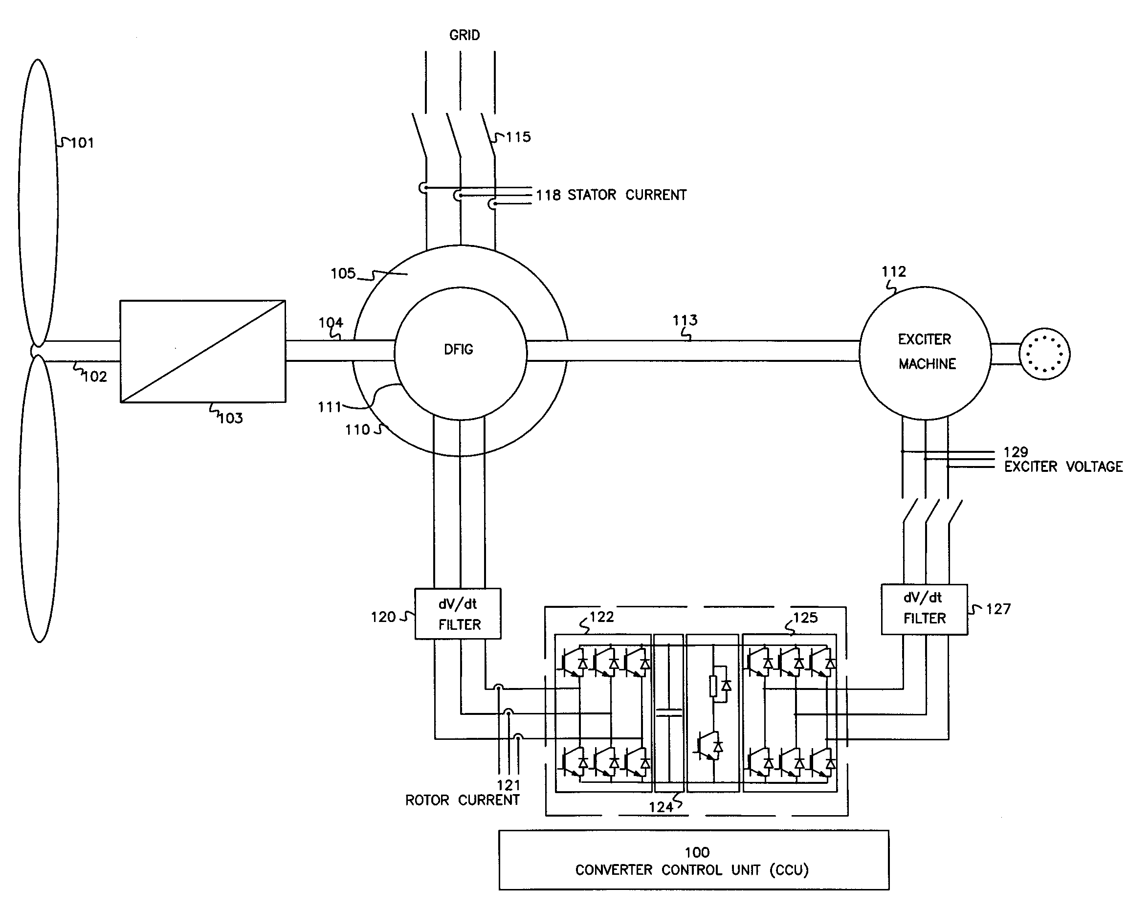
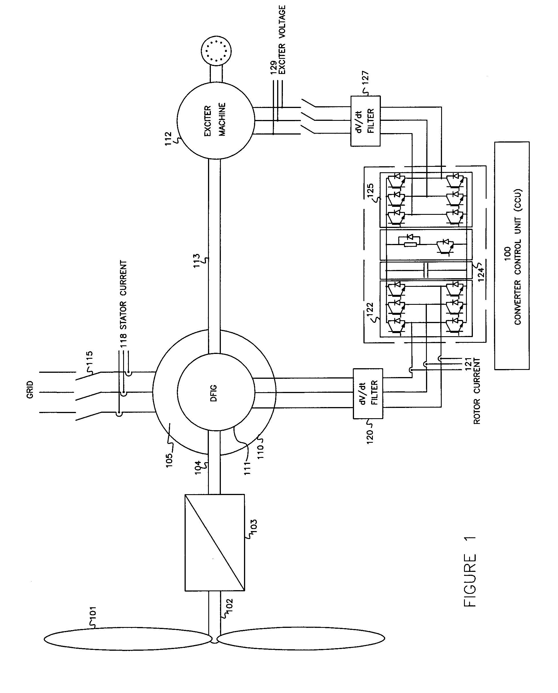
[0032]The variable speed wind turbine generator system is broadly shown in FIG. 1. In this exemplary embodiment, the variable speed system comprises one or more rotor blades (101) and a rotor hub which is connected to a drive train. The drive train mainly comprises a turbine shaft (102), a gearbox (103), a rotor shaft (104), and a doubly fed induction generator (105). The stator of the doubly fed induction generator (110) can be connected to the grid by using one or more contactors or circuit breakers (115). The system also comprises an exciter machine (112) such as an asynchronous machine, a DC machine, a synchronous (e.g. permanent magnet) machine,...


PUM


Abstract

A variable speed wind turbine having a doubly fed induction generator (DFIG) includes an exciter machine mechanically coupled to the DFIG and a power converter placed between a rotor of the DFIG and the exciter machine which guarantees a stable voltage to the power converter. Thus, the power converter is not directly connected to the grid allowing the continuous operation of the system during a low voltage event in the grid.

Description

1. BACKGROUND OF THE INVENTION[0001]1. Field of the Invention[0002]Methods and apparatuses consistent with the present invention relate to the field of variable speed wind turbines, and more particularly, to a variable speed wind turbine comprising a doubly fed induction generator (DFIG), an exciter machine, an intermediate static converter not connected to the grid and a control system to keep the doubly fed induction generator connected to the grid during a low voltage event, and a method implementing the same.[0003]2. Description of the Related Art[0004]In the last few years, wind power generation has increased considerably worldwide. For this reason, grid regulation companies have modified wind turbine electrical grid connection specifications in order to avoid disconnecting a wind turbine from the grid when a low voltage event or some kind of disturbance occurs in the grid. Thus, other new requirements are demanded of the wind turbines with respect to their contribution to the ...

Claims


Application Information

Patent Timeline
IPC IPC(8): F03D9/00H02P9/04
CPCF05B2270/10711H02P2101/15H02P9/102H02P9/007
Inventor RIVAS, GREGORIOGARMENDIA, IKERELORRIAGA, JOSUMAYOR, JESUSPEREZ BARBACHANO, JAVIERSOLE, DAVIDACEDO, JORGE
Owner INGETEAM POWER TECH
Learn More