
Bidet assembly for toilets

a technology forbidets and toilets, applied in baths, physical therapy, construction, etc., can solve the problems of requiring additional floor space forbidets, prone to water splashing, high manufacturing costs, etc., and achieves the effect of convenient installation, preventing water splashing out, and cleaning of user's private parts

Inactive Publication Date: 2008-07-03
UY WILLIAM CHENG
View PDF4 Cites 3 Cited by
  • Summary
  • Abstract
  • Description
  • Claims
  • Application Information

AI Technical Summary

Benefits of technology

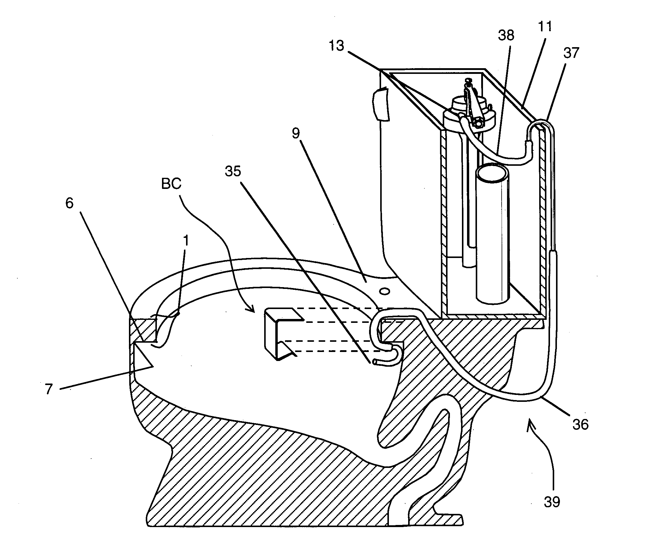
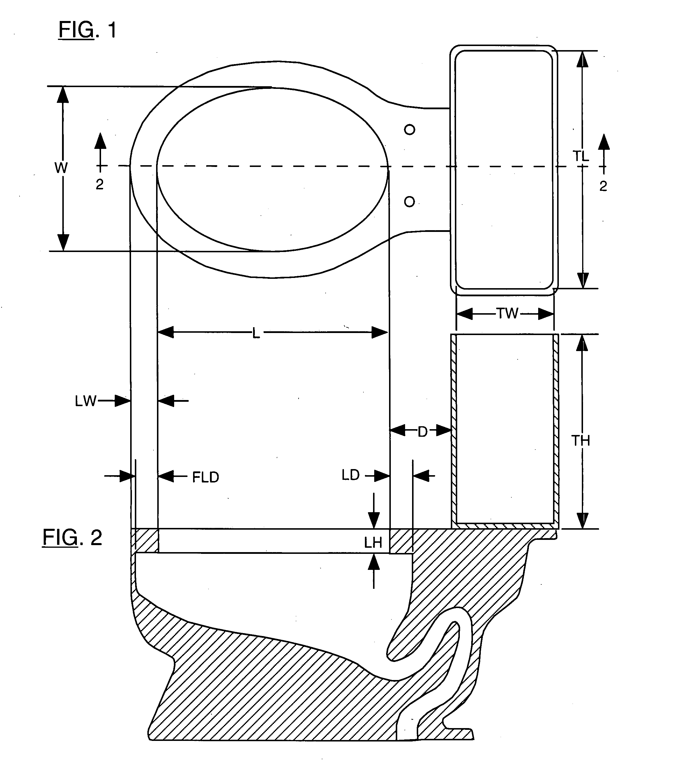
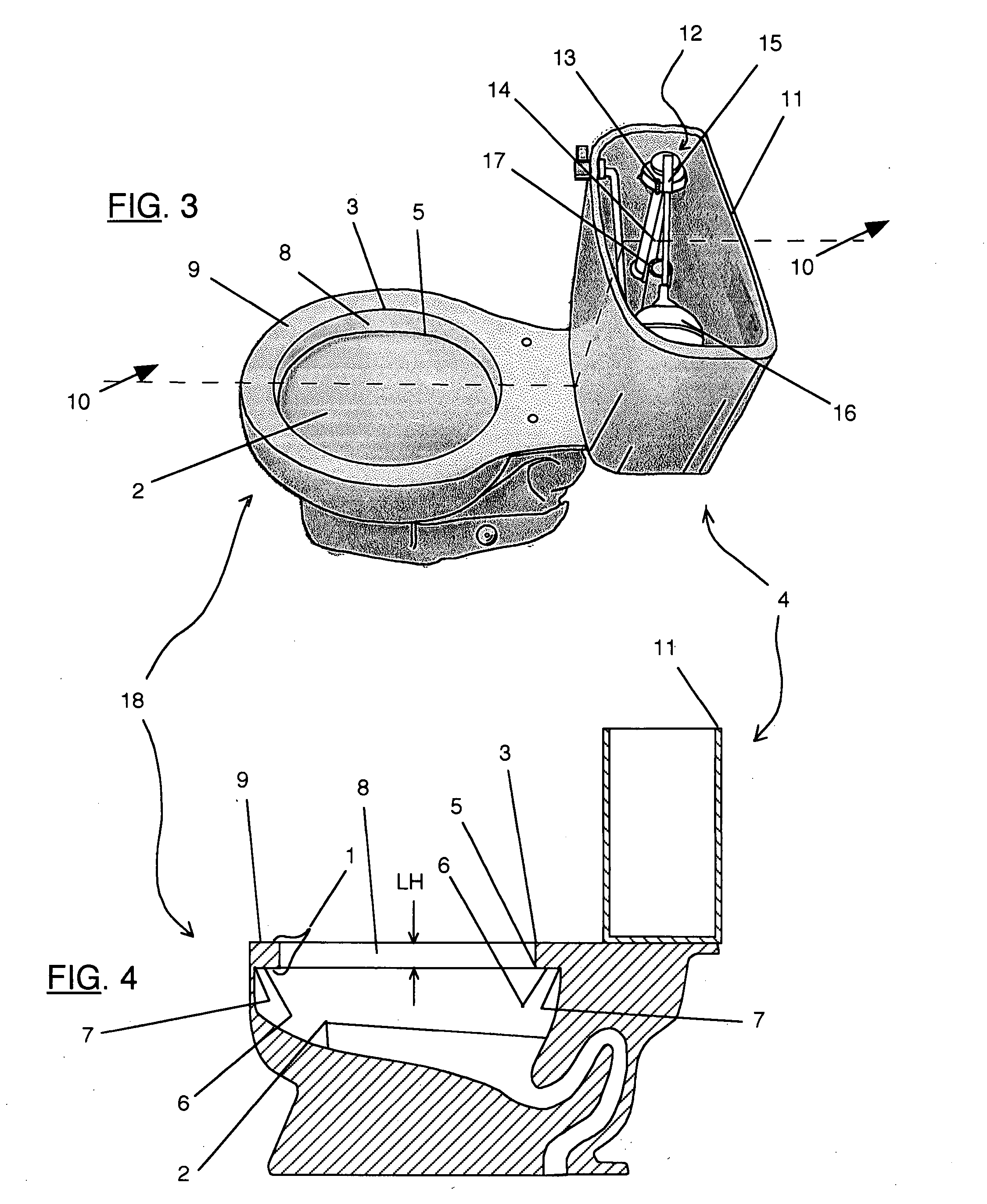
[0023]The present invention provides a bidet assembly for retrofitting toilets of all sizes and shapes to provide clean fine jet stream of water for the cleansing of a user's private parts while keeping water from splashing out of a toilet bowl without the use of any controlling devices. The bidet assembly of this invention comprises a nozzle connected to a water supply tube and a non-permanent mounting means for holding said nozzle inside a toilet bowl and under the bowl's lip horizontal surface. Said strategic placement of said nozzle keeps the jet stream of water within the bowl inner chamber (below its lip) and prevents water from splashing out. The bidet assembly of this invention is easily installed within the confines of a toilet tank and bowl, with most of its parts not visible, therefore it is not unsightly.

Problems solved by technology

Because bidet requires additional floor space and is also expensive, they are not installed in most homes.
All of the prior art bidet attachments, however, suffer at least one of the following deficiencies: prone to splash water out of toilet, expensive to manufacture, complex, permanent attachments, difficult to install and remove, leave mar or damage in toilet when bidet is removed, difficult to use, failure to meet sanitary requirements, and unsightly.
A major problem that is not obvious from reading the prior art and because it was not specifically addressed nor pointed out by the prior art is the propensity of splashing water out of a toilet bowl during the application of prior art devices.
The process becomes more complicated when it also requires the manipulation of a handle, valve, knob or other controls.
It becomes further more complicated, and may even be confusing, when a user gets up in the middle of the night, perhaps half asleep and in the dark, goes to the toilet and attempts to use such devices.
It becomes even further more difficult when such devices (U.S. Pat. Nos. 5,287,566, 5,722,097, 5,799,341) are located behind the user.
The prior art bidet device of U.S. Pat. No. 3,310,813 presented an unsanitary condition because its vertical spray nozzle is directly under the buttocks of a user.
However, these prior art bidets are still expensive (5,271,104), difficult to use (5,799,341), and unsightly (for all three said patents).
Such nozzles placement location presents two problems: First, said nozzles prevent some toilet seats from mating completely on the toilet bowl surface; Second, water shooting out from the, jet spray nozzle would spray outside a toilet bowl.
Therefore, its stand alone claim 1 is not a practical and viable solution.
However, this partial diversion of water is still insufficient to solve said problem.
Further attempt (claim 8) was made by this prior art to solve said problem by specifying “a means, such as an adjustable clamp, for restricting the flow of water.” A close / open clamp, as shown by this prior art, does not provide a good control for flow of water.
In any case, by adding a means of control complicates the device ease of use.
Said design is specific to a rim geometry and is impractical for general application as there is a myriad of sizes and shapes for a bowl top rim.
Other parts of the bidet attachment are located on top and also protruding out the side of a toilet bowl and are, therefore, unsightly.
This prior art is also incomplete as a complete bidet system as it only mentioned a pressurized liquid source without specifying what that source would be and it also mentioned that a valve may be necessary as a means for controlling the liquid flow.
All prior art bidet devices are unsightly because they are seen as clutter in a limited space toilet room, or can be seen as add-on on the side of a toilet or protruding out of a toilet in many places.
Making and inventorying a myriad of bidet sizes is impractical and expensive.
Unusual shape differences among models further contributed to the complexity.
It can be concluded from this myriad of sizes and shapes that designing a one-size bidet assembly - that will fit within the confines of any toilet - presents a major challenge to innovation.
Having a hot water source next to a toilet, however, is not common.
Installing a special heater adds further to the expense and complexity of a bidet assembly.

Method used


Image

  • Bidet assembly for toilets
  • Bidet assembly for toilets
  • Bidet assembly for toilets

Examples


example 1

[0137]The dimensions used for an actual sample toilet bowl are: A=17.75″, B=13.5″ (FIG. 5). These are the dimensions for the elliptical shape of a toilet bowl rear lip's corner edge 7. A straight steel threaded rod having size 10-24 and 0.192″ in diameter (made by Steel Works), purchased from Lowe's Home Improvement, was used for this experiment. A 22.6″ length, which is half the calculated-circumference, was used to wedge at the rear end of said bowl (FIG. 18). An equal length from each end-of said threaded rod was progressively cut and reinstalled to check for holding power until said rod can no longer stay up on the bowl surface. The results are shown in the following table:

LENGTH CUTFINALHOLDING ONTOFROM EACH ENDLENGTHBOWL SURFACEStart length22.6″YES1.0″20.6″YES0.5″19.6″YES0.5″18.6″YES0.5″17.6″YES1.0″15.6″YES1.0″13.6″NO

The minimum length is calculated taking 13.6″ divided by the circumference of 45.2″ and is equaled to 30.0%.

example 2

[0138]FIG. 32 shows two ellipses representing an actual toilet bowl opening (smaller elliptical shape) and the bowl's lip underside rear corner edge 7 (larger elliptical shape). Said larger elliptical shape of lip's underside rear corner edge 7 obviously can not be seen visibly and is drawn from measured values. In order to insert a long and stiff member into the inside surface of the larger elliptical shape of said bowl, the long and stiff member must first pass through the small bowl opening and this requires minimally bending it as represented by member 75. After passing through the bowl's opening, the ends are released and are restraint by the inside surface represented by the larger ellipse. Said long and stiff member would assume the position of member 76 after its release, assuming that it has enough spring-back property to reach this position represented by H2=7.900″. If the member has higher spring-back property, it would still be restraint but it would have a built-in flex...

example 3

[0139]In this example, the preferred embodiment example of an integral long and slender member bidet assembly of this present invention shown in FIG. 28 was fabricated using only common commercially available tools and merchandise to demonstrate low manufacturing cost. Said bidet assembly was fabricated using: ¼″ OD and 0.218″ ID 304 stainless steel tubing, ¼″ ID and ⅜″ OD PVC (polyvinyl chloride) clear flexible tubing, and quick connect (push-to-connect) ¼″ OD tube “T” fittings (Watts, North Andover, Mass.)

[0140]The objectives of quick and easy installation in this present invention of a bidet assembly is demonstrated by timing the speed to install and to remove said fabricated bidet assembly from a toilet. A total of five trials of installation and removal were done. It is assumed that a user would first read an installation instruction prior to actual installation. Therefore, the recorded time is the actual time to install and remove, not counting the time to read the instruction...


PUM


Abstract

A bidet assembly comprises at least one jet nozzle, connected to a multi-port tube fitting, which is connected to a water supply tube, which may comprise of four sections, and which is connected to the toilet bowl refill nipple, and a non-permanent mounting means. Said bidet assembly is a one-size-fits-all for retrofitting toilets of all sizes and shapes, has no moving parts, valves or controls and which provides fine jet streams of cool water spray - even from chilly cold water source - for cleansing a user's private parts during a toilet bowl refill cycle. Said bidet assembly is mounted inside and behind a toilet tank and inside a bowl and, therefore, is completely hidden from view and keeps water from splashing outside of the bowl. Said bidet assembly can be mounted or removed without tools, in less than two minutes and leaves neither mars nor damage on a toilet.

Description

REFERENCES CITED[0001]U.S. PATENT DOCUMENTS3,256,531June 1966Arensberg4 / 448  3,310,813May 1967Johnson4 / 448  3,943,961September 1976Knapp4 / 420.44,242,764January 1981Fukuda4 / 420.44,450,596May 1984Cohen4 / 447  4,691,391September 1987Kuo4 / 447  5,142,711September 1992Parikh4 / 420.45,247,711September 1993Kwon4 / 420.45,271,104December 1993LaTora4 / 420.45,287,566February 1994Azada4 / 420.45,652,971August 1997Wokas4 / 420.45,722,097February 1998Deveer4 / 420.45,799,341September 1998Rodas4 / 420.45,809,585September 1998Farshad4 / 443  5,953,766September 1999Szoke4 / 420.45,991,937November 1999Safara4 / 420.46,178,568January 2001Boulieris4 / 420.46,321,396November 2001Vallejo4 / 420.46,339,852January 2002Huang4 / 420.46,408,451June 2002Carn et al.4 / 420.46,473,913November 2002Bell4 / 448  6,526,602March 2003Jeon4 / 420.46,643,856November 2003Valverde4 / 420.46,704,946March 2004Mueller et al.4 / 420.46,785,915September 2004Daugherty4 / 448  6,843,432January 2005Philpott239 / 289   6,874,173April 2005Smith et al.4 / 420.46,978,492Dec...

Claims


Application Information

Patent Timeline
IPC IPC(8): A47K3/26
CPCE03D9/08
Inventor UY, WILLIAM CHENG
Owner UY WILLIAM CHENG
Learn More