
Electronic Battery Safety Switch

a safety switch and electronic technology, applied in the direction of electrical equipment, emergency protection arrangements for automatic disconnection, electric vehicles, etc., can solve the problems of disconnection of batteries, high short-circuit current, and particularly high risk of short-circuits, and achieve the effect of improving battery safety switches

Inactive Publication Date: 2008-06-26
CATEM DEVELEC
View PDF5 Cites 44 Cited by
  • Summary
  • Abstract
  • Description
  • Claims
  • Application Information

AI Technical Summary

Benefits of technology

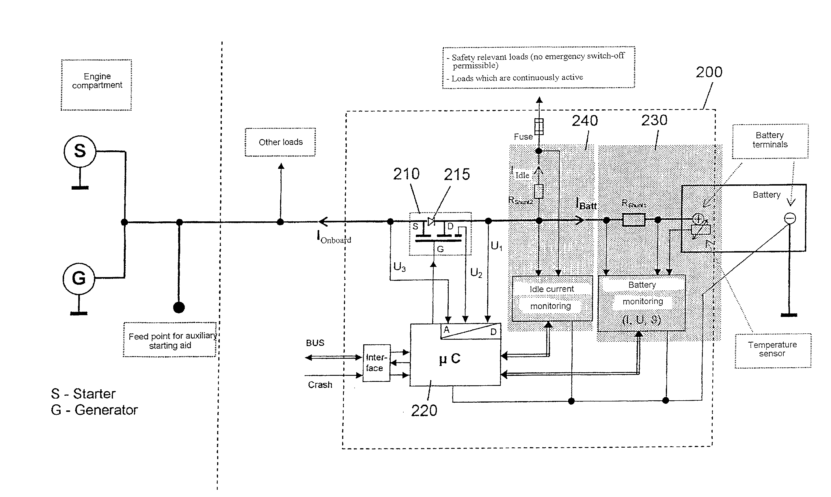
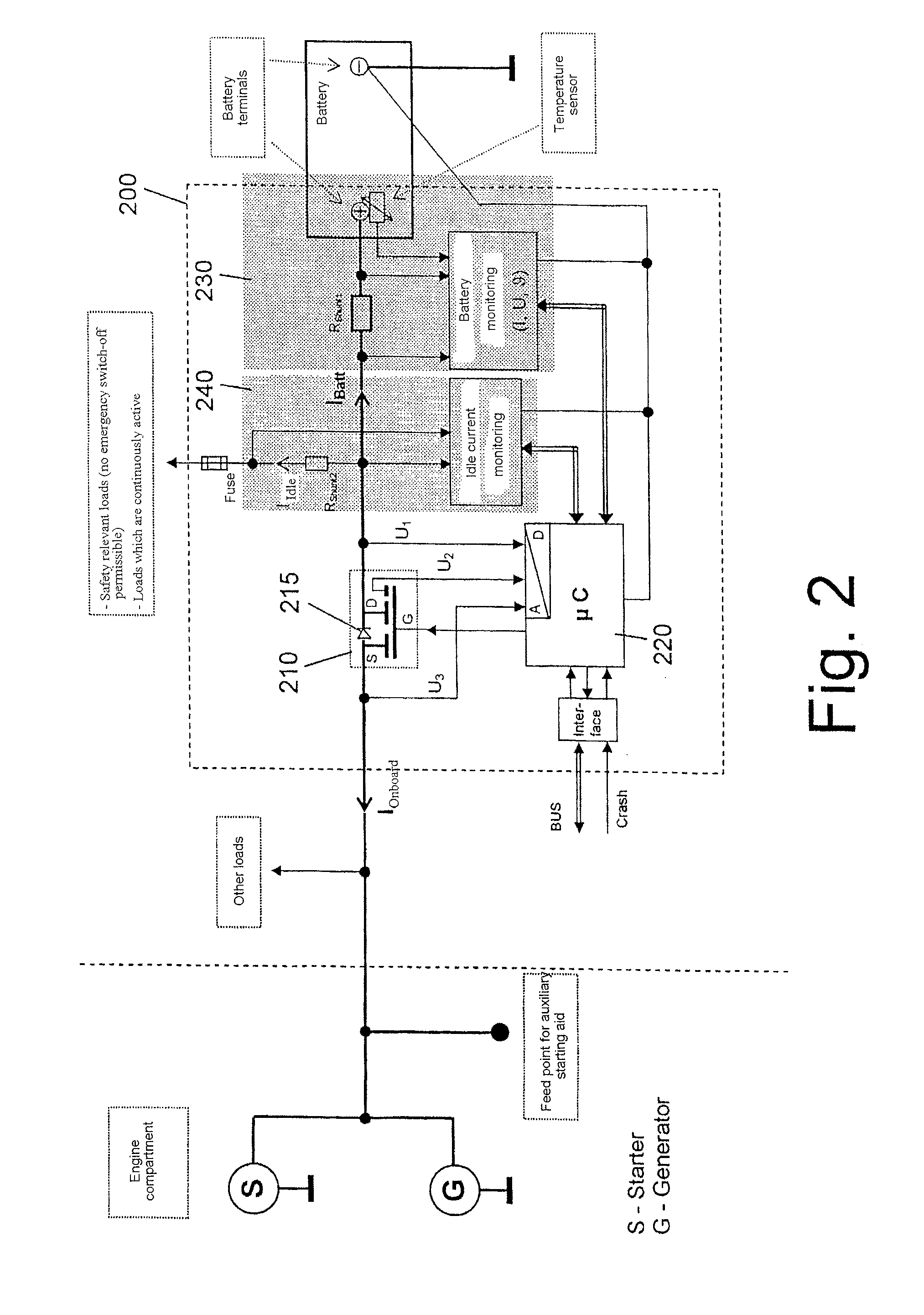
[0012]In the present invention a solid-state switch is used for the electrical connection or disconnection of the battery and the on-board network. In contrast to electromechanically actuated switching contacts, a solid-state switch facilitates an unlimited number of switching cycles. In addition a solid-state switch can be reset in a simple manner. With the battery safety switch according to the invention a disconnection needs therefore not be restricted like conventional ones to extraordinary emergencies.
[0026]Preferably the battery safety switch is equipped for mounting on a battery connection. The switch-off of the current feed to the on-board network can thus take place close to the battery and short circuits can be reliably prevented.

Problems solved by technology

The risk of a short circuit is particularly high with those motor vehicles which have the battery arranged at the rear of the vehicle.
The large cross-sectional areas lead to correspondingly high short-circuit currents during an accident.
A disadvantage with conventional battery safety switches is that the disconnection of the battery does not occur with those accident scenarios in which the air bag system is not activated.
With such an accident however, the high current wires in the floor panel of the motor vehicle are frayed through.
Once the battery safety switch has triggered, the motor vehicle cannot initially be driven, even after an accident without much consequential damage.
Due to the wear of the electromechanical contacts when switching high currents, these safety switches however only permit a very limited number of switchings, normally only a maximum of 10 to 50 switching actions.

Method used


Image

  • Electronic Battery Safety Switch
  • Electronic Battery Safety Switch
  • Electronic Battery Safety Switch

Examples


Embodiment Construction

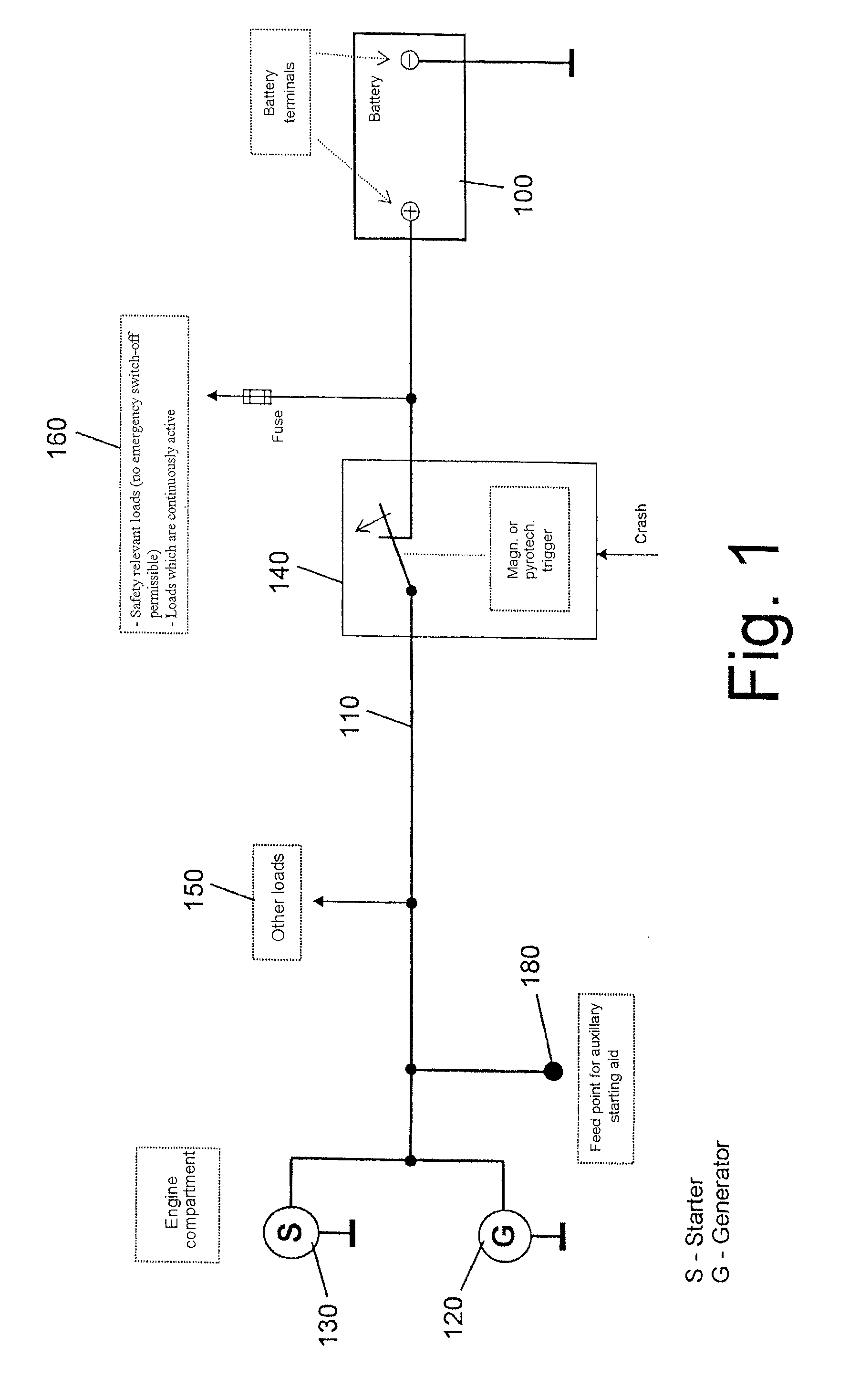
[0034]FIG. 1 shows in a schematic manner the structure of a conventional motor vehicle on-board network. The battery 100 is connected to the motor vehicle on-board network 110 via a battery safety switch 140. A generator 120, a starter 130 and other loads 150 are connected to the motor vehicle on-board network 110. An additional connection 180 is provided for the current feed for starting aids from other vehicles.

[0035]Whereas the generator 120 feeds electrical current to the motor vehicle on-board network 110 when the vehicle engine is running, the battery 100 stores the energy provided by the generator 120 during the operation of the engine. To put the engine into operation, a chemical reaction in the battery 100 produces electrical energy which is passed to the starter 130.

[0036]The battery safety switch 140 is actively switched off with the presence of an overcurrent signal or a crash signal. This means that with the application of a trigger signal the switch is opened either py...


PUM


Abstract

The invention relates to an electronic battery safety switch which facilitates a reliable and reversible disconnection of the motor vehicle on-board network from the battery. For this purpose an electronic solid-state switch is used which facilitates an unlimited number of switching cycles. The solid-state switch electrically disconnects the motor vehicle on-board network and the battery with the application of a crash signal or an overcurrent signal or when the ignition is switched off. With a parked vehicle an impermissibly high idle current and a discharge of the battery can be reliably prevented in an effective and simple manner. If the current flows from the on-board network in the direction of the battery, then the solid-state switch is switched actively conducting. Thus, damage to the switch in the inverse mode can be prevented.

Description

BACKGROUND OF THE INVENTION[0001]1. Field of the Invention[0002]The invention relates to an improved battery safety switch for motor vehicles.[0003]2. Description of the Related Art[0004]A battery safety switch is connected in motor vehicles between the battery and the motor vehicle on-board network. During an accident the battery safety switch disconnects the battery from the motor vehicle on-board network to prevent a fire or explosion being caused by escaping fuel and an electrical short circuit. The risk of a short circuit is particularly high with those motor vehicles which have the battery arranged at the rear of the vehicle. With these vehicles POSITIVE wires with a large cross-sectional area are located in the vehicle floor between the engine compartment and the rear of the vehicle. The large cross-sectional areas lead to correspondingly high short-circuit currents during an accident.[0005]Conventional battery safety switches facilitate an abrupt disconnection of the motor v...

Claims


Application Information

Patent Timeline
IPC IPC(8): B60R21/01H02H3/08B60R16/02B60R16/03H02H3/087H02J7/00
CPCB60R21/017B60R16/03B60R21/01
Inventor UHL, GUNTER
Owner CATEM DEVELEC
Learn More