
Magnetic element and magnetic core assembly having reduced winding loss

a technology of magnetic core and magnetic element, which is applied in the direction of magnetic cores/yokes, magnetic cores/inductances, transformer/inductance, etc., can solve the problem of inability to achieve transformer b>1/b>, and achieve the effect of reducing winding loss

Active Publication Date: 2008-06-26
DELTA ELECTRONICS INC
View PDF7 Cites 11 Cited by
  • Summary
  • Abstract
  • Description
  • Claims
  • Application Information

AI Technical Summary

Benefits of technology

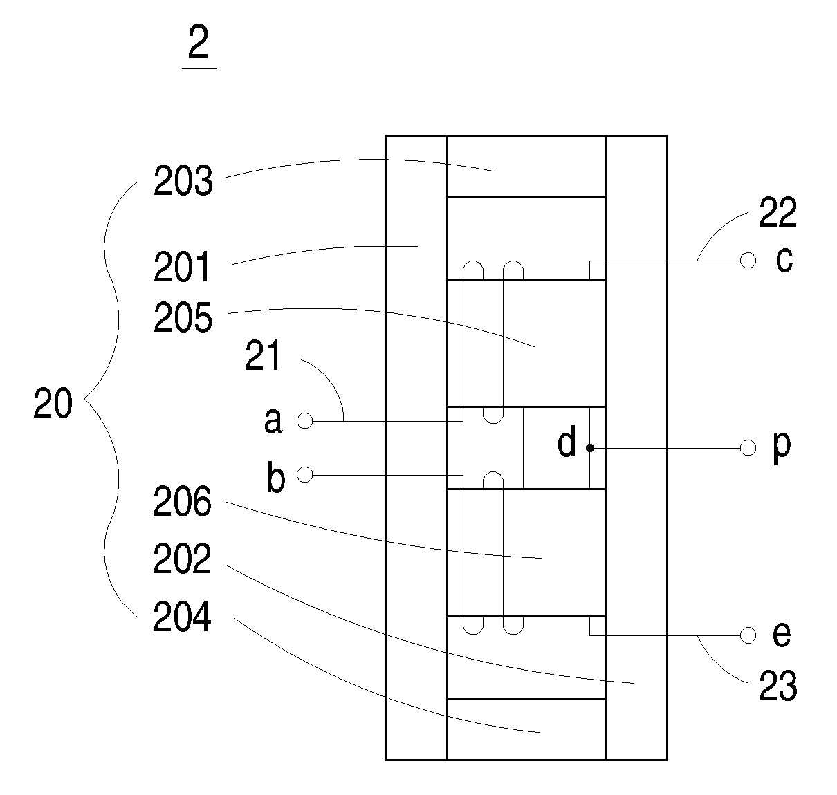
The present invention provides a magnetic element and a magnetic core assembly with reduced winding loss, overall volume and weight, AC magnetic flux variation, and leakage flux. The magnetic element includes a magnetic core assembly and multiple winding coils. The magnetic core assembly has a first side plate, a second side plate, a first side pillar, a second side pillar, and at least two middle pillars. The winding coils are wound around the at least two middle pillars. The technical effects of the invention include reduced winding loss, reduced overall volume and weight, reduced AC magnetic flux variation, and reduced leakage flux.

Problems solved by technology

On account of high operating efficiency and low power consumption, such a transformer 1 is not feasible.

Method used


Image

  • Magnetic element and magnetic core assembly having reduced winding loss
  • Magnetic element and magnetic core assembly having reduced winding loss
  • Magnetic element and magnetic core assembly having reduced winding loss

Examples


Embodiment Construction

[0020]The present invention will now be described more specifically with reference to the following embodiments. It is to be noted that the following descriptions of preferred embodiments of this invention are presented herein for purpose of illustration and description only. It is not intended to be exhaustive or to be limited to the precise form disclosed.

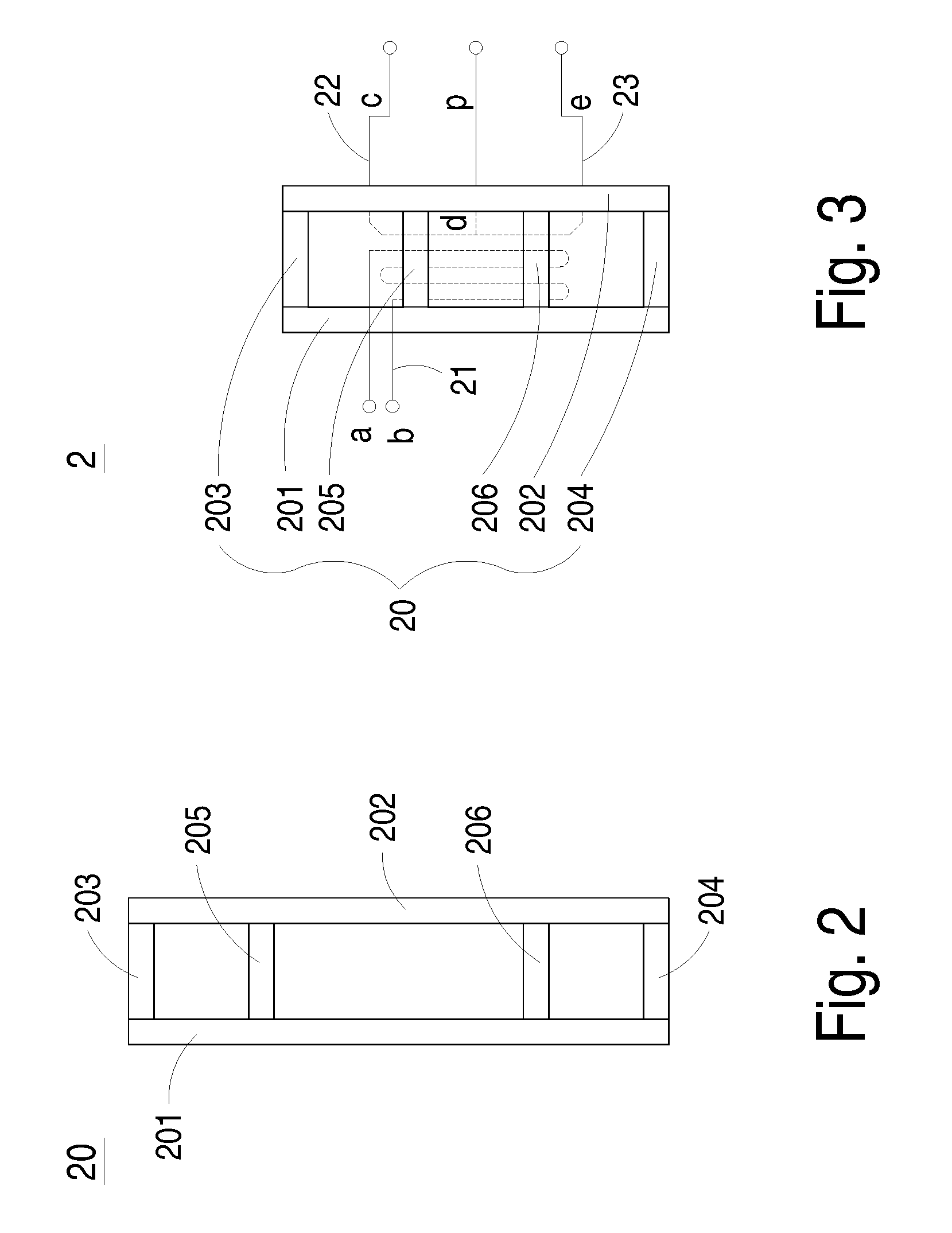
[0021]Referring to FIG. 2, a magnetic core assembly according to a preferred embodiment of the present invention is schematically illustrated. The magnetic core assembly 20 of FIG. 2 includes a first side plate 201, a second side plate 202, a first side pillar 203, a second side pillar 204 and at least two middle pillars such as a first middle pillar 205 and a second middle pillar 206. The first side pillar 203, the second side pillar 204 and the middle pillars 205, 206 are substantially parallel to each other, and perpendicular to the first side plate 201 and the second side plate 202. The first side pillar 203 and the second si...


PUM

PropertyMeasurementUnit
magneticaaaaaaaaaa
magnetic fluxaaaaaaaaaa
magnetic fluxesaaaaaaaaaa

Abstract

A magnetic element includes a magnetic core assembly and multiple winding coils. The magnetic core assembly is used for proving a closed magnetic flux path and includes a first side plate, a second side plate, a first side pillar, a second side pillar and at least two middle pillars. The first and second side pillars are arranged between the first and second side plates and respectively disposed on bilateral edges of the first and second side plates. The at least two middle pillars are arranged between the first and second side pillars and includes a first middle pillar and a second middle pillar. The winding coils are wound around the at least two middle pillars.

Description

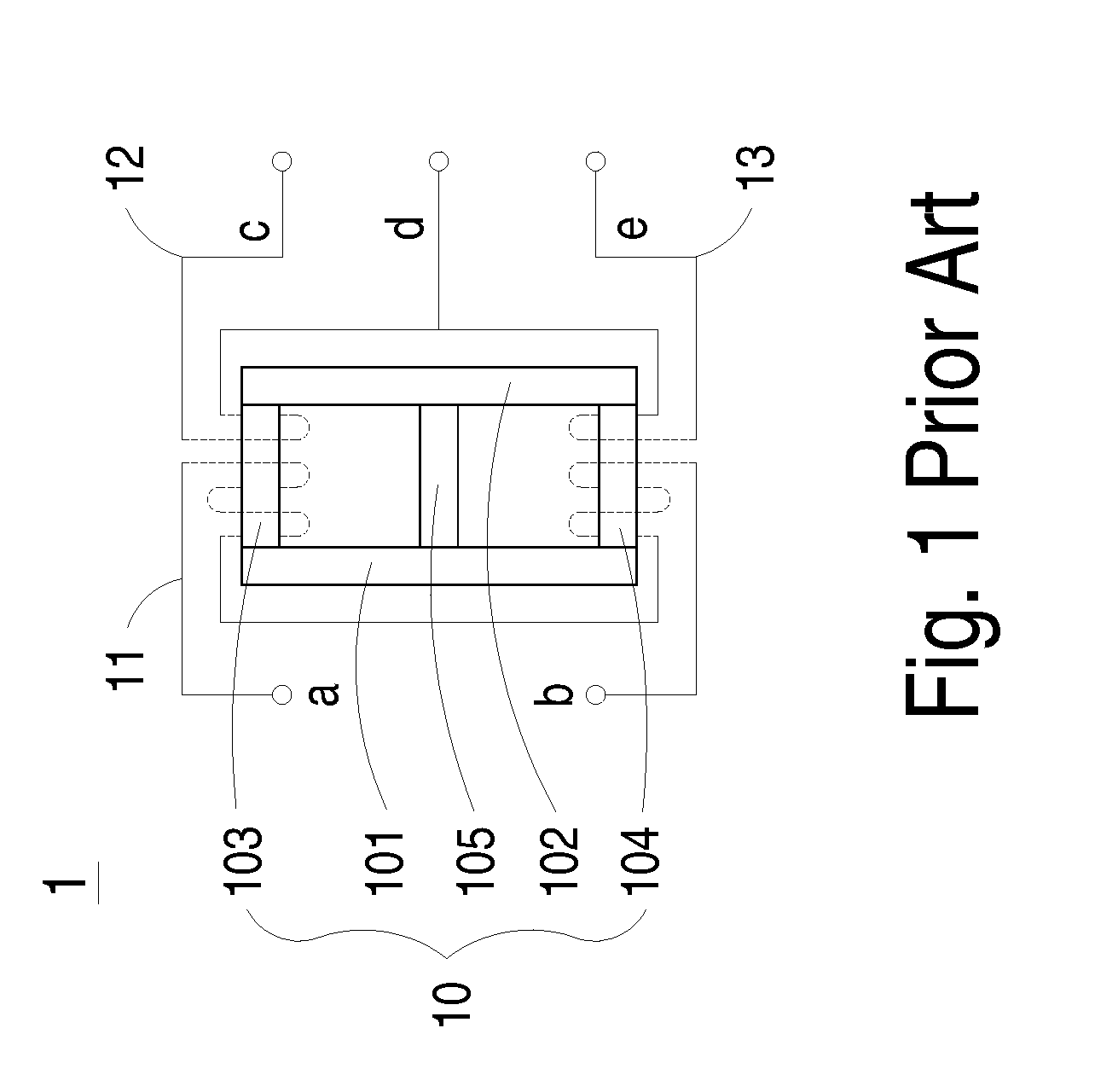
FIELD OF THE INVENTION[0001]The present invention relates to a magnetic element and a magnetic core assembly, and more particularly to a magnetic element and a magnetic core assembly with reduced winding loss.BACKGROUND OF THE INVENTION[0002]Nowadays, magnetic elements such as inductors and transformers are widely used in many electronic circuits to generate induced magnetic fluxes. Many conventional magnetic elements have magnetic core assemblies to form induced magnetic flux path. Depending on the material and the shapes of the magnetic core assembly, the magnetic properties of the magnetic elements are varied.[0003]Referring to FIG. 1, a conventional transformer including a magnetic core assembly and multiple winding coils is schematically illustrated. The transformer 1 of FIG. 1 comprises a magnetic core assembly 10 and several winding coils including for example a primary winding coil 11, a first secondary winding coil 12 and a second secondary winding coil 13. The magnetic cor...

Claims


Application Information

Patent Timeline
Patent Type & Authority Applications(United States)
IPC IPC(8): H01F17/00H01F27/28
CPCH01F3/10H02M7/003H01F27/38H01F27/346
Inventor LI, WEN-HUAHUANG, GUI-SONGFAN, HAI-FENGCHENG, JUI-CHUHSU, SU-CHIUNG
Owner DELTA ELECTRONICS INC
Learn More