
Fuel Injection System

a fuel injection system and high-pressure accumulator technology, applied in liquid fuel feeders, machines/engines, mechanical equipment, etc., can solve the problem of rapid pressure equalization between high-pressure accumulators, and achieve the effect of rapid pressure equalization

Inactive Publication Date: 2008-06-26
ROBERT BOSCH GMBH
View PDF15 Cites 1 Cited by
  • Summary
  • Abstract
  • Description
  • Claims
  • Application Information

AI Technical Summary

Benefits of technology

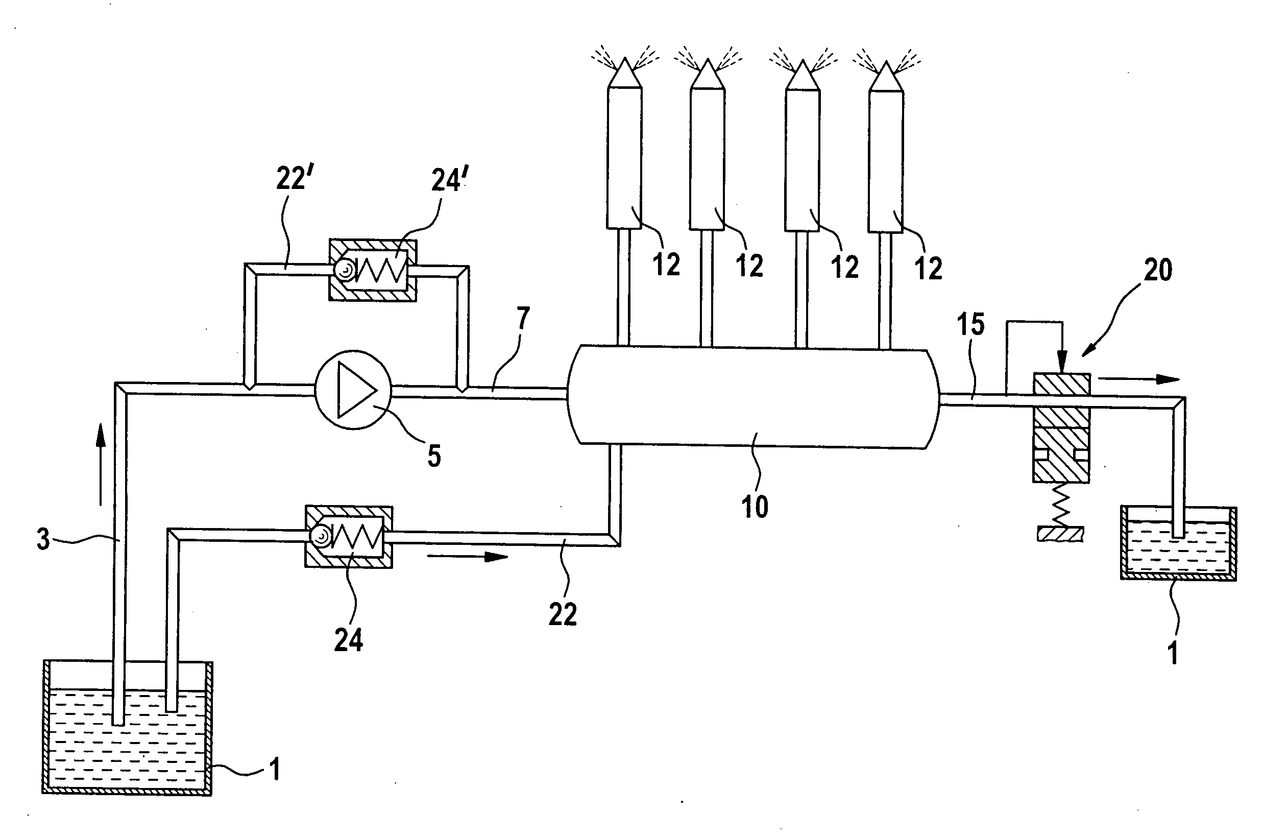
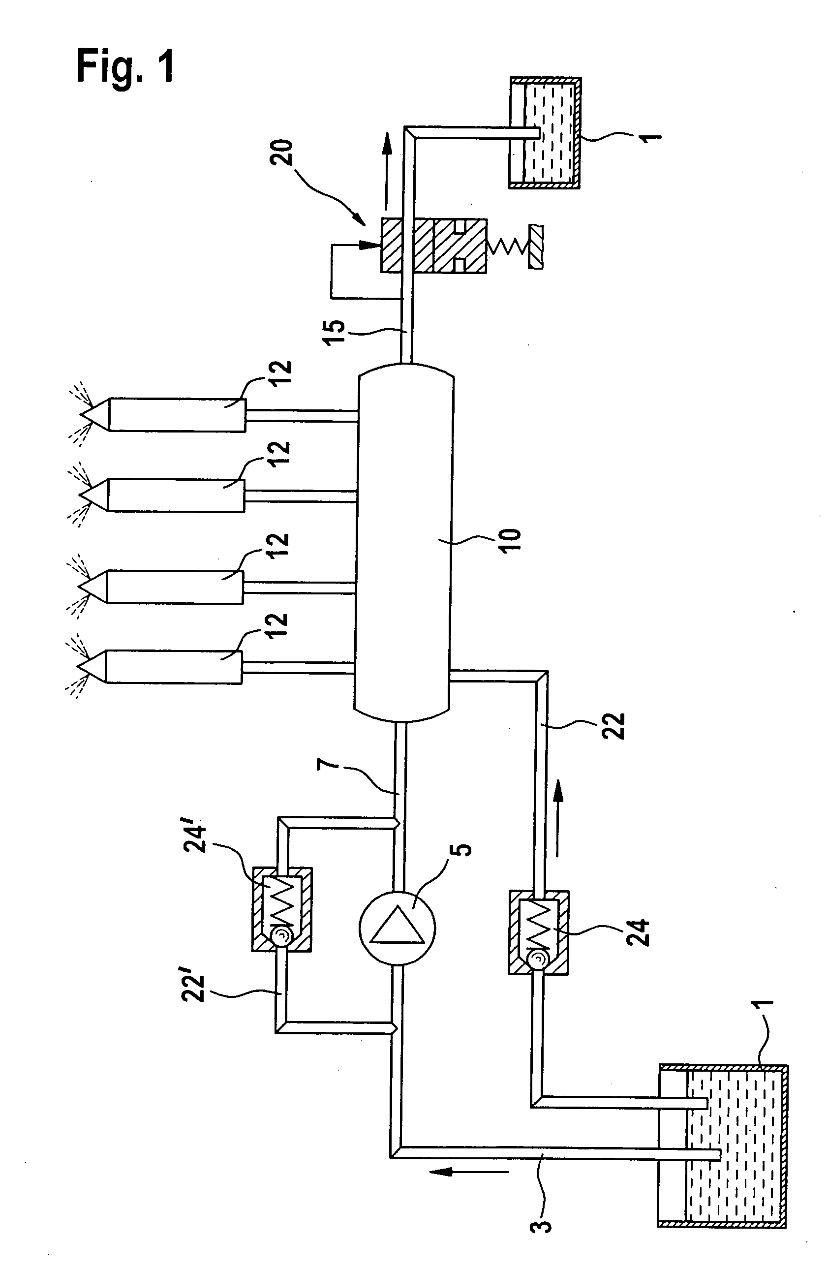
[0004]The fuel injection system according to the present invention has the advantage over the related art that the pressure buildup in a fuel injection system which operates according to the common rail principle occurs without noticeable delay. For this purpose a return line is implemented between the leak fuel area and the high-pressure accumulator, in which a regulating valve is implemented. The regulating valve operates in such a way that when the high-pressure pump is shut down, fuel may flow from the leak fuel area into the high-pressure accumulator. If the fuel in the high-pressure accumulator cools down, the cavity arising in the high-pressure accumulator due to the shrinkage of the fuel is filled up by fuel flowing in from the leak fuel area, so that the high-pressure accumulator always remains completely filled with fuel. Therefore, when the internal combustion engine is restarted and the high-pressure pump is thus started, no air has to be compressed, so that the pressure in the high-pressure accumulator increases very rapidly and is available for fuel injection.

Problems solved by technology

This results in rapid pressure equalization between the high-pressure accumulator and the leak fuel chamber.

Method used


Image

  • Fuel Injection System
  • Fuel Injection System
  • Fuel Injection System

Examples


Embodiment Construction

[0012]FIG. 1 schematically shows a fuel injection system which operates using a common rail system. Fuel is provided at ambient pressure in a leak fuel area 1, leak fuel area 1 typically corresponding to the fuel tank in a vehicle. An intake line 3 leads from leak fuel area 1 to a high-pressure pump 5, in which fuel may be generated at high pressure. The fuel compressed at high pressure is supplied by high-pressure pump 5 via a high-pressure line 7 to a high-pressure accumulator 10, in which the fuel may be stored under high pressure. Connected to high-pressure accumulator 10 are multiple fuel injectors 12 via which the fuel which is stored in high-pressure accumulator 10 at high pressure may be injected into the combustion chamber of the internal combustion engine. Via corresponding regulating devices in high-pressure pump 5, it is generally provided that only as much fuel is supplied to high-pressure accumulator 10 as is taken therefrom for fuel injection. If too high a pressure n...


PUM


Abstract

A fuel injection system having a high-pressure accumulator, in which fuel may be stored at high pressure, at least one fuel injector via which the fuel located in the high-pressure accumulator may be injected into the combustion chamber of an internal combustion engine being connectable to the high-pressure accumulator. A high-pressure pump draws in fuel out of a leak fuel area, compresses it, and supplies it to the high-pressure accumulator, so that a high fuel pressure is built up therein during operation of the high-pressure pump. A return line having a regulating valve is implemented between the leak fuel area and the high-pressure accumulator, the regulating valve allowing a fuel flow from the leak fuel area into the high-pressure accumulator when the high-pressure pump is shut down.

Description

FIELD OF THE INVENTION[0001]The present invention is directed to a fuel injection system.BACKGROUND INFORMATION[0002]A fuel injection system is known, for example, from German Published Patent Application No. 100 60 812 and is preferably used for internal combustion engines. Such a fuel injection system has a high-pressure accumulator, in which fuel may be stored at high pressure. Connected to the high-pressure accumulator is at least one fuel injector via which the fuel provided at high pressure in the high-pressure accumulator may be injected into the combustion chamber of an internal combustion engine. A high-pressure pump, which draws in the fuel out of a leak fuel area and supplies it in compressed form to the high-pressure accumulator, is provided for producing the high pressure in the high-pressure accumulator. During operation of the high-pressure pump, a fuel pressure which is required for finely atomized fuel injection is thus built up in the high-pressure accumulator.[000...

Claims


Application Information

Patent Timeline
Patent Type & Authority Applications(United States)
IPC IPC(8): F02M63/00F02M69/54F02M55/00F02M55/02F02M63/02
CPCF02M55/002F02M55/007F02M2200/60F02M63/0225F02M63/025F02M55/025
Inventor SCHEURER, HANS-PETERBUSCH, ROGER
Owner ROBERT BOSCH GMBH
Learn More