Method and Control Unit for Protecting a Clutch in a Drivetrain of a Motor Vehicle

a technology of a control unit and a drivetrain, which is applied in the direction of brake action initiation, braking system, position/direction control, etc., can solve the problems of completely different values of the clutch torque, and achieve the effect of reducing the clutch torque, reducing the torque value, and high rotational speed

Inactive Publication Date: 2008-06-19
DR ING H C F PORSCHE AG
View PDF8 Cites 10 Cited by
  • Summary
  • Abstract
  • Description
  • Claims
  • Application Information

AI Technical Summary

Benefits of technology

[0012]A first advantage of the invention is that the clutch torque is reduced for the purpose of protecting the clutch not purely in a precautionary, and therefore in many cases unnecessary, fashion, but rather that a reduction takes place only when a thermal overload of the clutch is actually impending.
[0013]A further advantage results from the fact that interventions which take place according to the invention irritate the driver intuitively less than would be the case in the case of a restriction in clutch torque independently of the rotational speed difference. If, in contrast, the torque is limited without a limitation of the rotational speed difference, it is possible, with the same release of heat in the clutch, for a smaller torque value to be given at a relatively high rotational speed difference. The relatively high rotational speed difference is associated, assuming identical initial clutch rotational speeds, with a higher engine rotational speed, which leads the driver, who initially allows the clutch to slip, to expect a larger torque than is actually available when he closes the clutch. The driver intuitively assumes that the engine provides the optimum torque associated with the present rotational speed, which is however not the case on account of the limitation of the torque. This can therefore result overall in a power behavior which is irritating to the driver.
[0014]In the case of the invention, although the driver must also accept a power loss, the power loss is however in line with the perceived rotational speed level, and therefore does not lead to irritation. The invention therefore results in a clearer, intuitively perceptible feedback of reactions of the vehicle to a clutch actuation by the driver. The clutch is therefore protected effectively overall. Improved drivability is given here in comparison with other interventions. The improved drivability, together with the restriction in the interventions to actually necessary cases, ensures better acceptance of the clutch protective function by the driver.
[0015]In accordance with an added mode of the invention, there is step of determining the temperature of the friction clutch using a mathematical model from operating parameters of the drivetrain. The operating parameters include at least values of the clutch torque and of the rotational speed difference across the friction clutch.
[0016]In accordance with a further mode of the invention, there is the step of monitoring as to whether the friction clutch is actuated, and carrying out the method only if the friction clutch is actuated.
[0017]In accordance with another mode of the invention, there are the steps of limiting a permanent slip when the friction clutch is not actuated and determining the rotational speed difference from rotational speed values of an engine rotational speed sensor, of a transmission rotational speed sensor and / or of a wheel rotational speed sensor of the motor vehicle.

Problems solved by technology

This can result in completely different values of the clutch torque.

Method used


Image

  • Method and Control Unit for Protecting a Clutch in a Drivetrain of a Motor Vehicle
  • Method and Control Unit for Protecting a Clutch in a Drivetrain of a Motor Vehicle
  • Method and Control Unit for Protecting a Clutch in a Drivetrain of a Motor Vehicle

Examples


Embodiment Construction

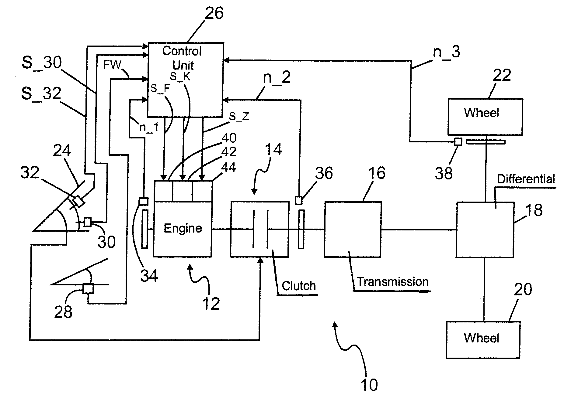
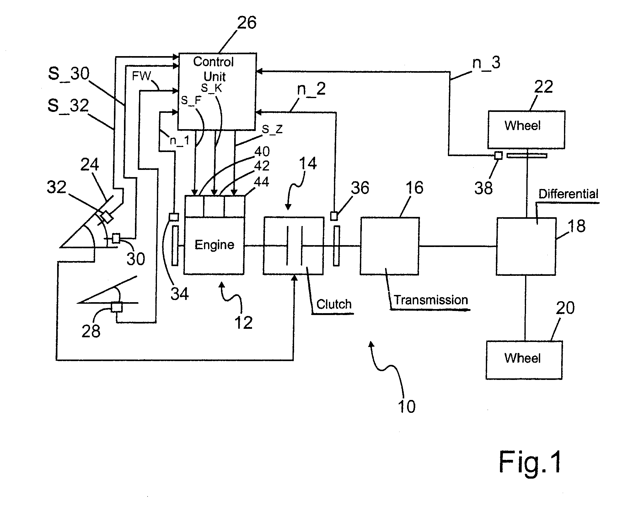
[0025]Referring now to the figures of the drawing in detail and first, particularly, to FIG. 1 thereof, there is shown a drivetrain 10 of a motor vehicle having an internal combustion engine 12, a clutch 14, a variable-speed transmission 16, a differential 18 and drive wheels 20, 22. The clutch 14 is a friction clutch which is actuated by the driver of the motor vehicle. Conventional friction clutches have at least one driver plate which is pressed by a spring-loaded pressure plate against a flywheel of the internal combustion engine 12. The driver plate is connected in an axially movable but rotationally fixed manner to a transmission input shaft. In the closed state of the clutch 14, the torque of the internal combustion engine 12 is, by a force-fitting action, transferred into the driver plate of the clutch 14 and transmitted from there to the transmission input shaft.

[0026]The actuation of the clutch 14 takes place counter to the spring loading. In this application, an actuation...


PUM


Abstract

A method controls an internal combustion engine in a drivetrain of a motor vehicle. The drivetrain has a variable-speed transmission and a friction clutch which is to be actuated by the driver. By use of the friction clutch a force-fitting action between the internal combustion engine and the variable-speed transmission is controlled, with it being possible for the clutch torque of the internal combustion engine to be reduced in order to protect the clutch from thermal overloading. A temperature of the clutch is determined, a limit value which is dependent on the determined temperature is determined and a rotational speed difference across the clutch is determined. The clutch torque is reduced if the rotational speed difference approaches or reaches or exceeds the temperature-dependent predetermined limit value. A control unit is set up to carry out a method of this type or to control its process.

Description

CROSS-REFERENCE TO RELATED APPLICATION[0001]This application claims the priority, under 35 U.S.C. § 119, of German application DE 10 2006 058 724.3-26, filed Dec. 13, 2006; the prior application is herewith incorporated by reference in its entirety.BACKGROUND OF THE INVENTIONField of the Invention[0002]The present invention relates to a method for controlling an internal combustion engine in a drivetrain of a motor vehicle, which drivetrain has a variable-speed transmission and a friction clutch which is to be actuated by the driver. By use of the friction clutch, a force-fitting action between the internal combustion engine and the variable-speed transmission is controlled, with it being possible for the clutch torque of the internal combustion engine to be reduced in order to protect the clutch from thermal overloading. The invention also relates to a control unit which is set up to control an internal combustion engine in a drivetrain of a motor vehicle. The drivetrain has a vari...

Claims


Application Information

Patent Timeline
Patent Type & Authority Applications(United States)
IPC IPC(8): G06F7/00
CPCB60W10/02B60W10/06B60W30/186F02D2250/26F02D41/1497F02D2250/18F02D41/022
Inventor REIHER, MARCUSBAUR, PETER
Owner DR ING H C F PORSCHE AG
Why Eureka
Try Eureka