
Hazardous material transportation railcar and cask craddle

Inactive Publication Date: 2008-06-19
PRIVATE FUEL STORAGE
View PDF5 Cites 13 Cited by
  • Summary
  • Abstract
  • Description
  • Claims
  • Application Information

AI Technical Summary

Benefits of technology

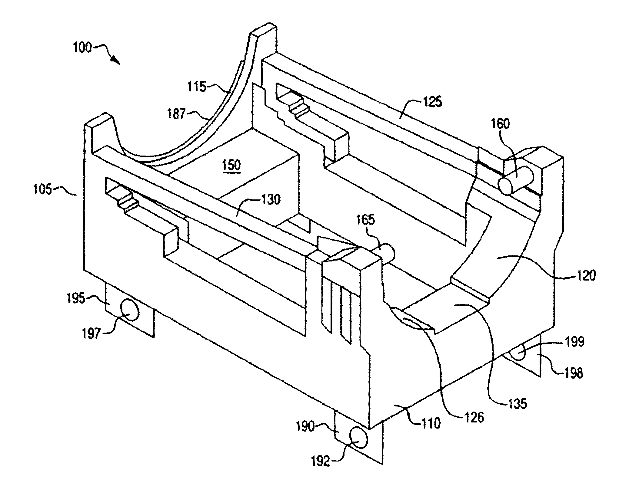
[0012]The cradle in accordance with the invention includes the main structure of the cradle which supports the dead weight and dynamic loads from the transportation cask, restraining members which restrain the transportation cask from an upward movement as well as horizontal movements, and a rotational support member which allows the transportation cask to be placed in the vertical position onto the cradle and rotated to the horizontal position for final transportation. The main structure of the cradle supports both the weight of the cask as well as the dynamic loads that will be experienced during transportation of the cask. The restraining members are designed to provide adequate support to protect the cask including protection to the cask from the cradle allowing the cask to be exposed to loads in excess of the maximum cask design load (i.e., The restraining members will fail at a lower force than the maximum design force for the cask which will allow the impact absorbers located on the ends of the cask to prevent the cask from receiving a force greater than the design of the cask itself). Thus, the cradle design provides support to protect the spent fuel transportation cask and also to protect the cask should it be exposed to loads that would exceed the design load for the cask. In accordance with the invention, the cradle will be secured to the railcar in four locations to accommodate the camber in the railcar flatbed. This will reduce potential failure of the cradle to railbed connection.
[0014]The cradle and railcar in accordance with the invention are designed together so as to provide a high level of assurance against structural failure of the railcar and cradle combination.
[0016]The invention also provides a nylon bearing surface affixed to load bearing brace as well as a stop bar affixed to the load bearing brace to prevent longitudinal movement of the cask.
[0018]The invention also provides an uplift prevention device affixed to the first top section of the first non-load bearing brace and the second top section of the second non-load bearing brace which prevents upward (vertical) movement of the cask.

Problems solved by technology

Generally, there is limited storage space in a nuclear reactor's spent fuel pool or in its hot cell.
By transporting fewer failed fuel rod assemblies, even if some fissionable material escapes from the failed fuel rods and accumulates near other fissionable material in the container, there is not enough fissionable material in the entire container to pose a significant risk of criticality.
The problem with the foregoing solution, though, is it wasteful of resources, because significantly fewer failed fuel rod assemblies can be transported per container relative to the number of undamaged fuel rod assemblies that can be transported in the same container.
The problem with this solution, however, is that the method is inefficient for three principle reasons.
First, the failed fuel rod assemblies be broken up.
Second, such containers are capable only of transporting comparatively few failed fuel rod assemblies.
The other major problem with transporting spent nuclear fuel is that United States law imposes stringent safety requirements even on containers used to transport undamaged fuel rod assemblies.
Nonetheless, the cask / canister method cannot be used for transportation in areas accessible to the public because they fail to meet the requirements imposed by U.S. law.

Method used


Image

  • Hazardous material transportation railcar and cask craddle
  • Hazardous material transportation railcar and cask craddle
  • Hazardous material transportation railcar and cask craddle

Examples


Embodiment Construction

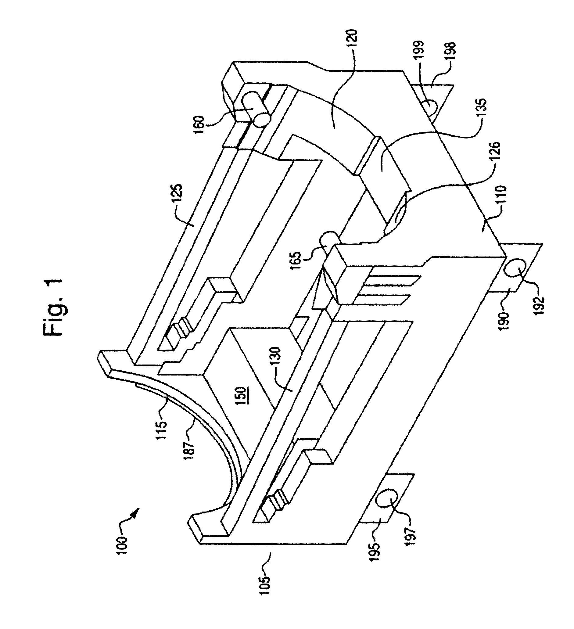
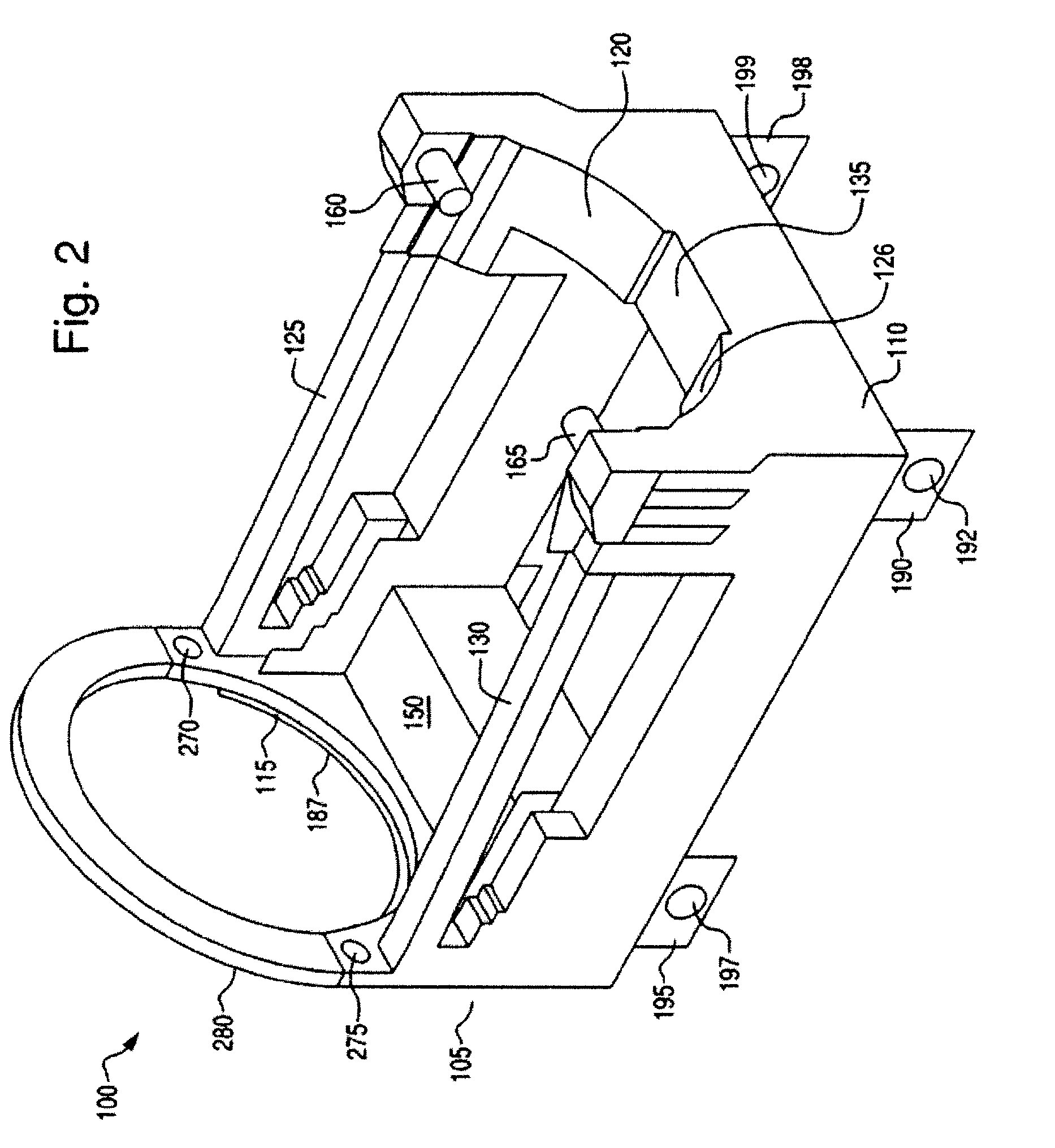
[0027]FIG. 1 shows a perspective view of a cradle 100 for transporting spent nuclear fuel or other hazardous materials in accordance with an embodiment of the invention. As will be described in greater detail below, the cradle 100 is configured to securely receive a spent fuel transportation cask (not shown in FIG. 1). FIG. 1 shows a front cradle section 105 and a rear cradle section 110. The front cradle section 105 is connected to the rear cradle section 110 via a first horizontal support 130 and a second horizontal support 125. The first horizontal support 130 and the second horizontal support 125 provide support and stability to the cradle 100. The front cradle section 105 includes a front load bearing brace 115. The front load bearing brace 115 has a semicircular shape to accommodate the shape of the transportation cask. The front load bearing brace 115 has a nylon bearing surface (not visible in FIG. 1) on its top surface that provides bearing surface for the cask. Thus, the n...


PUM


Abstract

The invention provides an apparatus for safely transporting various hazardous materials, including spent nuclear fuel. The invention includes a cask cradle that is configured to securely receive a cask for containment of hazardous materials, such as spent nuclear fuel. The cask cradle in accordance with the invention includes a front cradle section load bearing brace, a rear cradle section having a first non-loading bearing brace and a second non-loading brace, first and second horizontal support members connecting the front cradle section to the rear cradle section and trunnions that lock into and retain the cask. The invention also provides a railcar having a depressed flatbed region for receiving and securely retaining the cask cradle. The railcar also includes a variety of sensors that monitor various aspects of the railcar performance, including braking performance sensors, sensors for truck hunting, rocking and vertical, lateral and longitudinal acceleration, a Global Positioning Satellite (GPS) sensor and wheel bearing sensors corresponding to each of the wheel bearing assemblies.

Description

BACKGROUND OF THE INVENTION[0001]1. Field of the Invention[0002]The invention relates to an apparatus for safely transporting spent nuclear fuel and other hazardous materials and, more particularly, to a rail transportation system for safely transporting spent nuclear fuel and other hazardous waste materials to interim storage facilities, transfer points, or to a final federal disposal site, the rail transportation system including a railcar and cask cradle.[0003]2. Description of the Related Art[0004]Nuclear reactors and storage sites for radioactive materials have been in operation for many years. In a nuclear reactor, the fissionable material gradually becomes spent and must be removed along with other radioactive byproducts. Since the spent fuel contains fission by products which are highly radioactive and which generate large amounts of heat, the spent fuel is usually temporarily stored in the reactor's spent fuel pool. The spent fuel pool is a pool of water of sufficient volum...

Claims


Application Information

Patent Timeline
IPC IPC(8): B60P7/12
CPCB61D3/16B61D45/00G21Y2004/30G21Y2002/305G21F5/14
Inventor LISENBY, JOHN DAVE
Owner PRIVATE FUEL STORAGE
Learn More