
Digital Broadcasting Transmitting System For Conditional Access and Method Thereof, and Digital Broadcasting Receiving Terminal and Method Thereof

a digital broadcasting and transmitting system technology, applied in broadcast system control, television system, specific applications, etc., can solve the problems of repeater service provider generating installation and maintenance costs, commercial broadcasting system cannot exist, and no appropriate treatment of the charged service has been provided up to now

Active Publication Date: 2008-06-19
KT CORP
View PDF5 Cites 14 Cited by
  • Summary
  • Abstract
  • Description
  • Claims
  • Application Information

AI Technical Summary

Benefits of technology

[0013]The present invention has been made in an effort to provide a digital broadcast transmission system and a method thereof, and a digital broadcast receiving terminal and a method thereof having advantages of controlling charged subscribers and free subscribers to receive a desired service within the coverage of the main broadcasting network and controlling charged subscribers to receive a desired service within the coverage of the repeating network in a broadcasting network having a single frequency network or a multiple frequency network.

Problems solved by technology

When no mutual stability system is guaranteed between the transmitter and the receiver in the above-noted digital broadcasting, the commercial broadcasting system cannot exist.
However, when a main broadcasting network service provider is different from a repeater service provider, the repeater service provider generates the cost of installing and maintaining a broadcasting network in the shade region, and the repeater service provider charges for the usage of the repeating network.
That is, the repeater service must be a charged service for the purpose of activating the repeating network, but no appropriate treatment for the charged service has been provided up to now.

Method used


Image

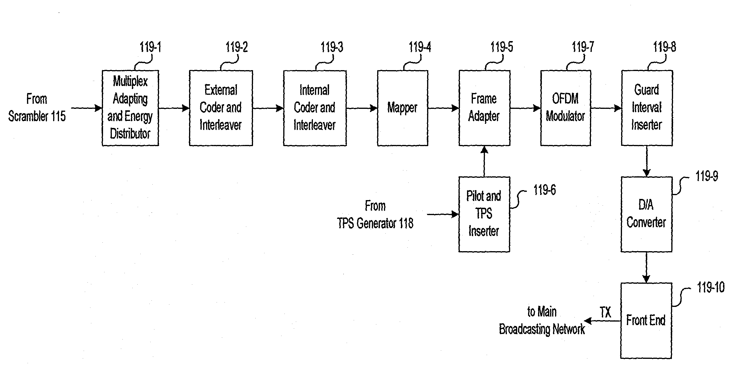
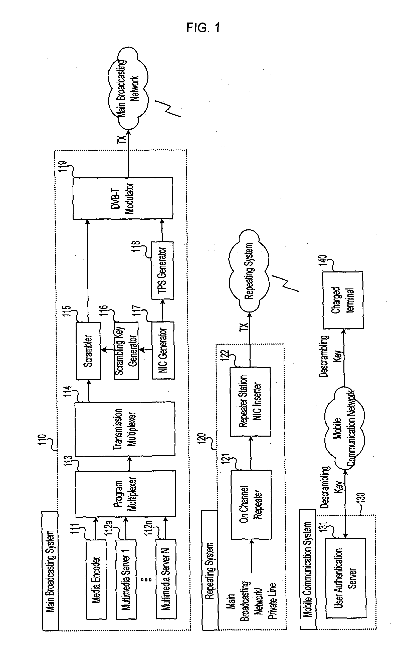
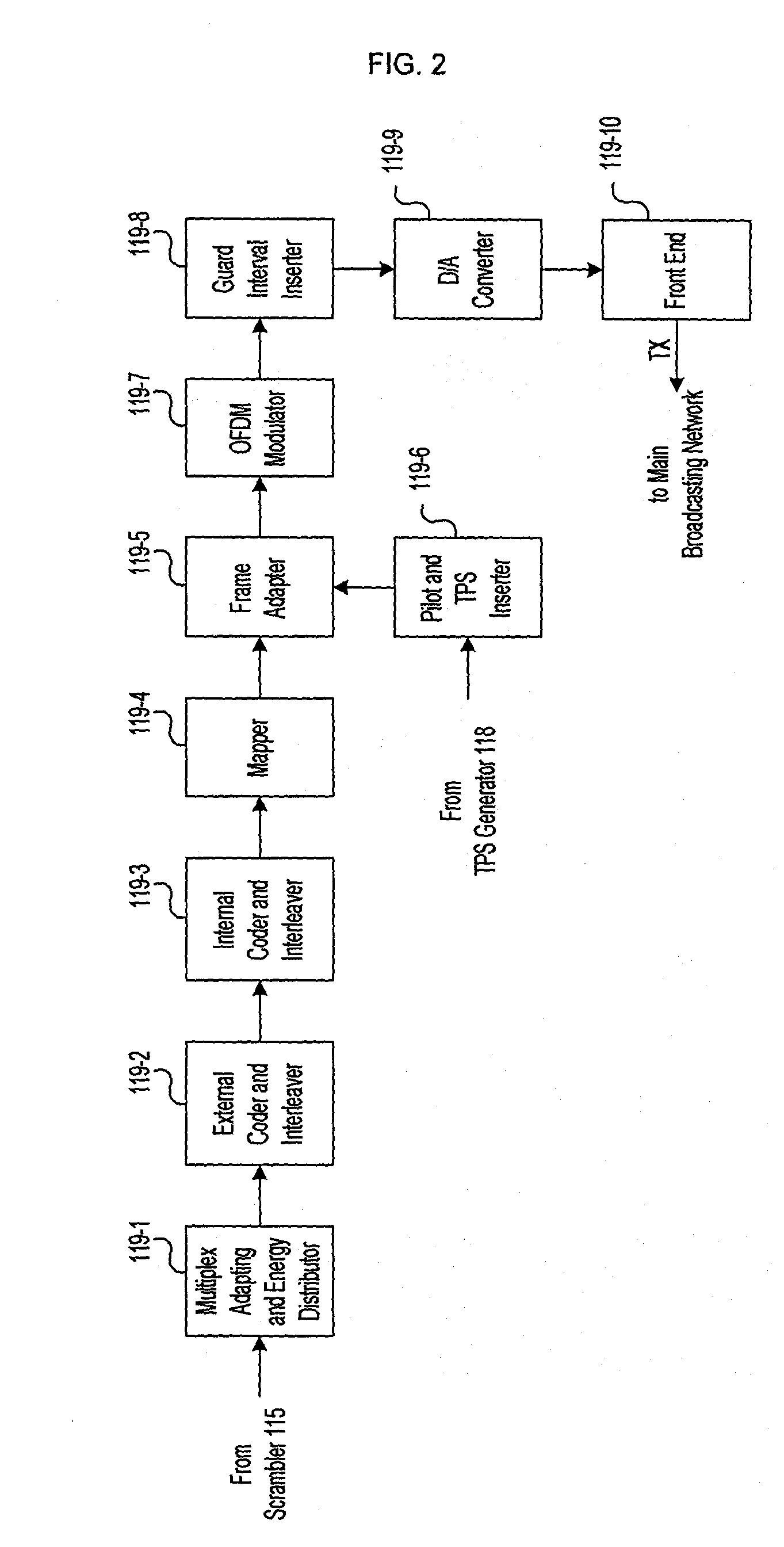
  • Digital Broadcasting Transmitting System For Conditional Access and Method Thereof, and Digital Broadcasting Receiving Terminal and Method Thereof
  • Digital Broadcasting Transmitting System For Conditional Access and Method Thereof, and Digital Broadcasting Receiving Terminal and Method Thereof
  • Digital Broadcasting Transmitting System For Conditional Access and Method Thereof, and Digital Broadcasting Receiving Terminal and Method Thereof

Examples


Embodiment Construction

[0030]An exemplary embodiment of the present invention will hereinafter be described in detail with reference to the accompanying drawings.

[0031]Referring to the drawings, a conditional access transmission system and method thereof, and a receiving terminal and a method thereof according to an embodiment of the present invention will now be described in detail.

[0032]The embodiment of the present invention discloses a digital broadcasting conditional access system (CAS) for controlling conditional access for respective transmitters by scrambling the data packets transmitted to a subscriber and applying part of the transmission parameter signaling (TPS) carriers, that is, network identification codes (NICs), used for transmitting parameters of transmission data as key values of transmitted data packets in the DVB-T system.

[0033]In other words, a digital broadcasting system for controlling a receiver to restrict access to each transmitter according to transmission service providers whe...


PUM


Abstract

Disclosed are a conditional access transmission system and method, and a receiving terminal and method. The transmission system transmits scrambled broadcasting signals including a network identification code (NIC) in the digital broadcasting service. A repeating system repeats the broadcasting signals transmitted by the transmission system to a subscriber station. In this instance, the NIC of the repeating system is different from that of a main broadcasting network. A receiving terminal descrambles the scrambled broadcasting signals by using the NIC and a descrambling key. According to the present invention, the charged subscriber can receive broadcasting signals or TPEG messages in the repeating network.

Description

BACKGROUND OF THE INVENTION[0001](a) Field of the Invention[0002]The present invention relates to a conditional access system (CAS), and in particular, it relates to a digital broadcast transmitting system and method for providing a conditional access to a user by each broadcasting service provider when there are plural broadcasting service providers, and a digital broadcasting receiving terminal and a method thereof in a single or multiple frequency network.[0003](b) Description of the Related Art[0004]Digital broadcasting has characteristics of providing multiple channels, high quality, and multiple functions. In particular, development of multiplexing techniques has enabled concurrent combination of images, speech, and data irrespective of contents, size, and transmission thereof, and has formed a return channel through a modem to allow interactive services. Accordingly, digital data broadcasting has overcome the problems of conventional analog broadcasting and has provided multi...

Claims


Application Information

Patent Timeline
Patent Type & Authority Applications(United States)
IPC IPC(8): H04N7/167
CPCH04H20/06H04H20/55H04H60/23H04N21/238H04N21/43853H04N21/23895H04N21/4345H04N21/438H04N21/4382H04N21/2383H04N7/04
Inventor HONG, CHUNG-PYO
Owner KT CORP
Learn More