
Rotor winding shield for a superconducting electric generator

a superconducting electric generator and winding shield technology, applied in the direction of superconductor devices, magnetic circuit rotating parts, magnetic circuit shapes/forms/construction, etc., can solve the problems of premature degradation and winding failure, material can carry a substantial electric current for a long duration with insignificant energy loss, and mechanically massive and electrically complex structure of generators

Inactive Publication Date: 2008-06-19
SIEMENS ENERGY INC
View PDF17 Cites 6 Cited by
  • Summary
  • Abstract
  • Description
  • Claims
  • Application Information

AI Technical Summary

Problems solved by technology

The generator is a mechanically massive and electrically complex structure, supplying output power up to 2,222 MVA at voltages up to 27 kilovolts.
Since the superconducting materials exhibit substantially no electrical resistance when maintained at or below their critical temperature, these materials can carry a substantial electric current for a long duration with insignificant energy losses.
Disadvantageously, the HTS rotor windings are sensitive to mechanical bending and tensile stresses that can cause premature degradation and winding failure (e.g., an open circuit).
These over-speed and fault conditions substantially increase the centrifugal force loads on the rotor coil windings beyond the loads experienced during normal operating conditions.
This flux can generate a significant torque on the rotor core and the HTS winding, potentially damaging the HTS winding and its support structures.
In addition to the undesired mechanical forces produced by these transient torques, any magnetic field coupled into the rotor windings causes undesired alternating current (AC) losses in the HTS conductors.
Although rotor winding support structures can be designed to allow the HTS conductors to withstand the additional torque introduced by these transient magnetic fields, such support structures increase the support mass and may introduce additional undesired thermal paths between the warm rotor core and the cold HTS windings.
However, it is a substantial challenge to manufacture, assemble and balance a large and continuous cylindrical shield structure with the precision and tolerances required for a large electrical generator.
Further, the considerable rotor weight tends to cause rotor sag.
These effects lead to fretting damage due to relative motion (albeit a small displacement) at the interface of the rotor core and the non-magnetic shield.
The cumulative effect of the interface contact forces and the vibration forces create extremely high stresses on the rotating non-magnetic shield.
If the rotor core and the HTS rotor windings are enclosed in a vacuum vessel (comprising stainless steel for example) additional design difficulties arise.
Joining the dissimilar metals of the vacuum vessel and the shield is problematic.
Further, the disadvantages associated with the large generator shield discussed above are exacerbated by the addition of the vacuum vessel.
But such a process increases production cycle time and process costs.
Undoubtedly, the lower temperature affects the rotor's balance.

Method used


Image

  • Rotor winding shield for a superconducting electric generator
  • Rotor winding shield for a superconducting electric generator
  • Rotor winding shield for a superconducting electric generator

Examples


Embodiment Construction

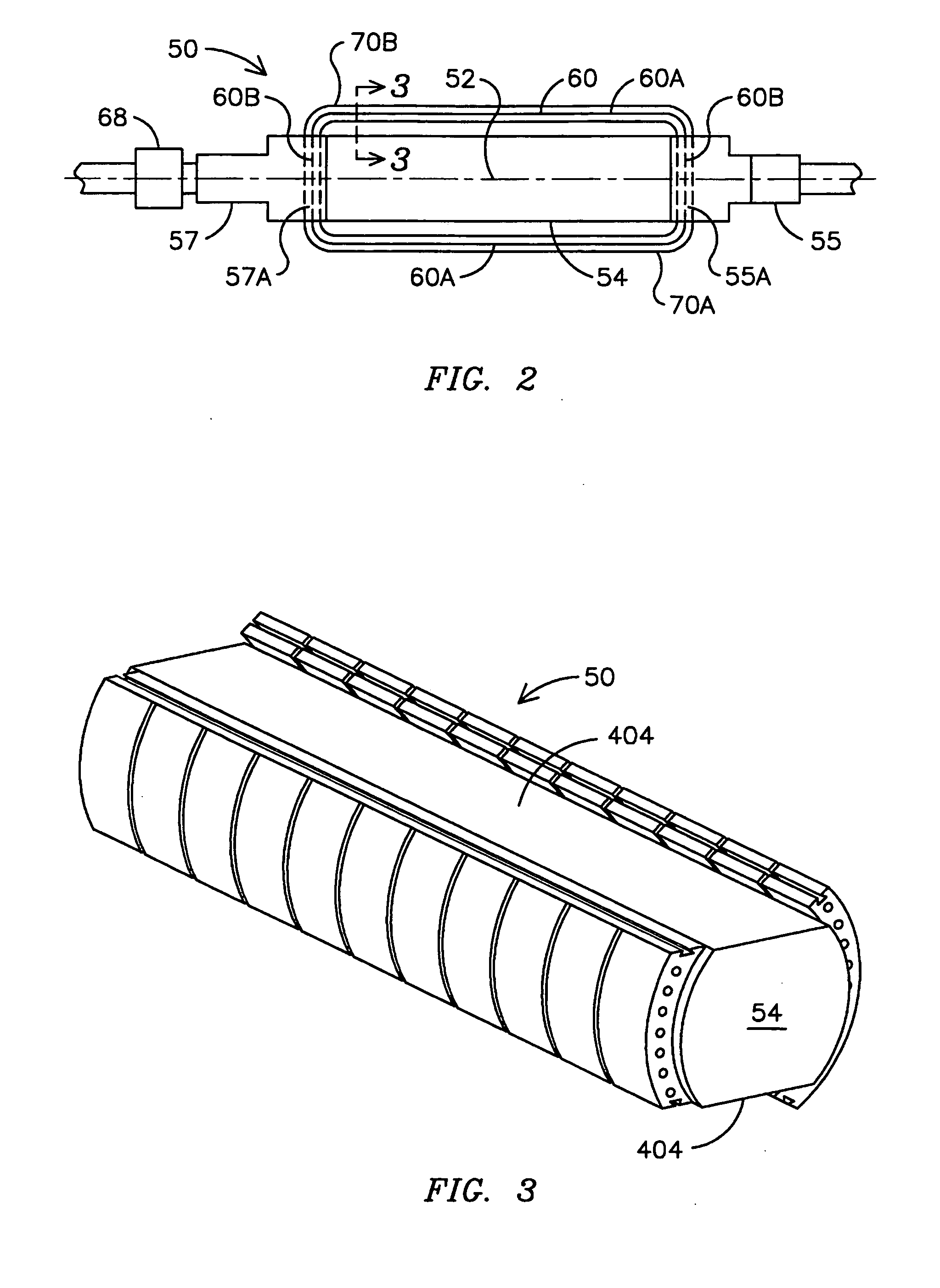
[0027]Before describing in detail the particular non-magnetic rotor winding shield in accordance with the present invention, it should be observed that the present invention resides primarily in a novel and non-obvious combination of hardware elements and method steps. Accordingly, these elements and steps have been represented by conventional elements and steps in the drawings, showing only those specific details that are pertinent to the present invention so as not to obscure the disclosure with details that will be readily apparent to those skilled in the art having the benefit of the description herein.

[0028]The following embodiments are not intended to define limits as to the structures or methods of the invention, but only to provide exemplary constructions. The embodiments are permissive rather than mandatory and illustrative rather than exhaustive.

[0029]A rotor shield of the present invention overcomes the various limitations described above. The shield of the present invent...


PUM


Abstract

A generator rotor core (54) carrying superconducting windings (60) and having a shield (426) over the superconducting windings (60) to prevent external magnetic fields from impinging the windings. Axial shield edges (430 / 434) mate with corresponding features of the rotor core (54) or with structures affixed to or supported by the core (54) to support the shield (426).

Description

FIELD OF THE INVENTION[0001]The invention relates generally to superconducting generators and specifically to a non-magnetic rotor shield for protecting superconducting rotor windings and optimizing the production of magnetic flux generated by the rotor windings.BACKGROUND OF THE INVENTION[0002]An electric generator transforms rotational energy into electrical energy according to generator action principles of a dynamoelectric machine. The turning torque supplied to a rotating rotor by a combustion or steam-driven turbine is converted to alternating current (AC) electricity, typically three-phase AC, in a stationary stator that surrounds the rotor. The generator is a mechanically massive and electrically complex structure, supplying output power up to 2,222 MVA at voltages up to 27 kilovolts. Electrical generators are the primary power producers in an electrical power system.[0003]As shown in the cross-sectional view of FIG. 1, a conventional electric generator 10 comprises a substa...

Claims


Application Information

Patent Timeline
IPC IPC(8): H02K3/42H02K1/04H02K1/22
CPCH02K1/24H02K11/0005Y02E40/625H02K2205/12H02K55/04H02K11/012Y02E40/60
Inventor ZHANG, JIPINGNELSON, ROBERT J.CLAYTON, PETER J.MCCOWN, WILLIAM R.
Owner SIEMENS ENERGY INC
Learn More