
Lid body anchor system

a technology of fixing mechanism and body, which is applied in the direction of fastening means, mechanical devices, instruments, etc., can solve the problems of slow computer processing speed, low f performance efficiency, and low price, and achieve simple mechanical design, enhance labor saving efficiency of attaching/detaching, and operate easily

Inactive Publication Date: 2008-06-12
INVENTEC CORP
View PDF2 Cites 1 Cited by
  • Summary
  • Abstract
  • Description
  • Claims
  • Application Information

AI Technical Summary

Benefits of technology

[0011]In views of the disadvantages of the prior art mentioned above, it is a primary objective of the present invention to provide a lid body fixing mechanism, which is labor saving and easy to operate.
[0012]It is another objective of the present invention to provide a lid body fixing mechanism, which provides an easy means of attachment / detachment.
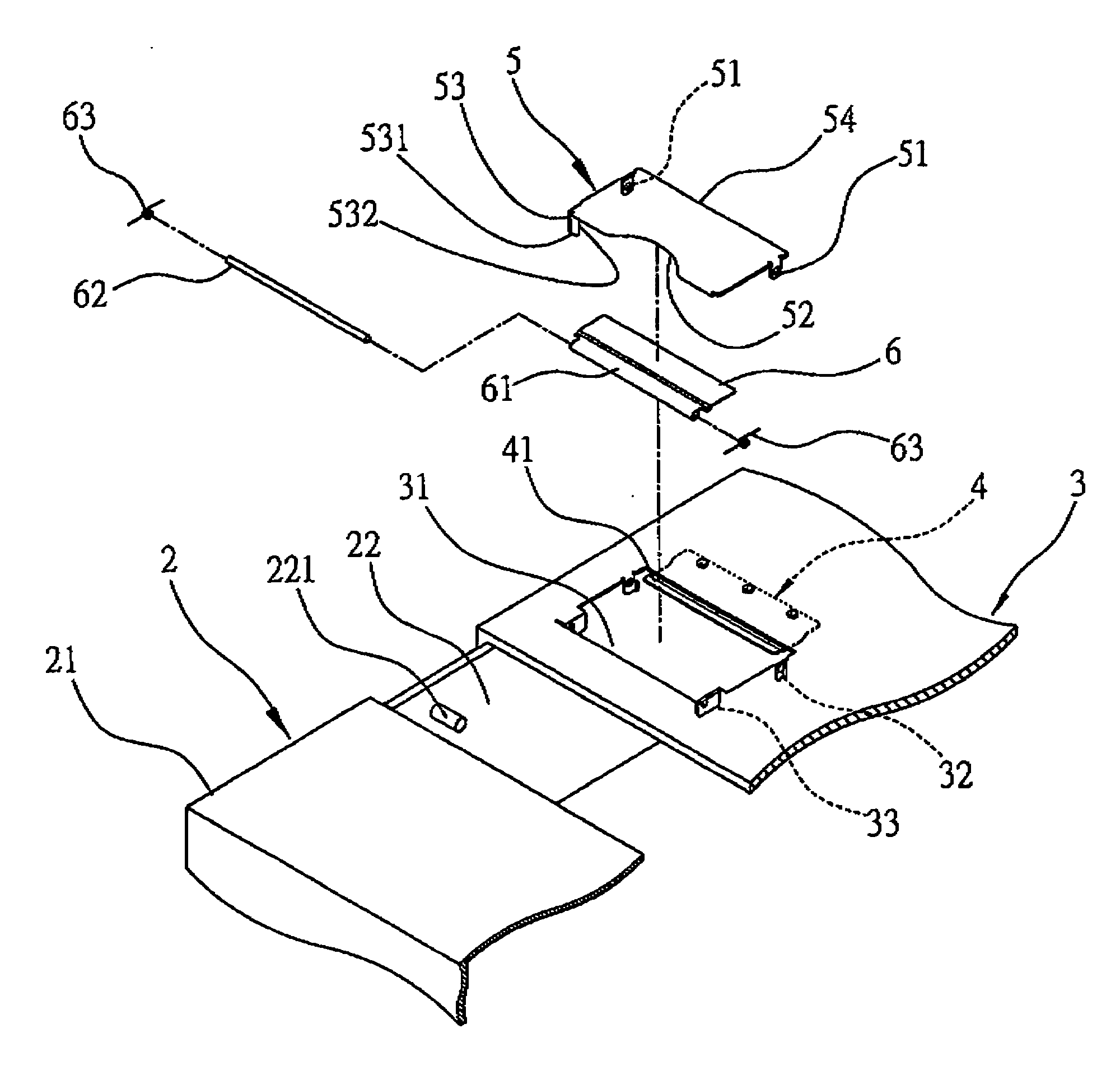
[0014]To achieve the above-mentioned and other related objectives, a lid body fixing mechanism is provided according to the present invention, the lid body fixing mechanism is capable of fixing a lid body that covers the opening of a mechanical housing, and the lid body has a through hole, the lid body fixing mechanism includes: a blocking unit, which is located on an inner wall of the mechanical housing and is corresponding to the through hole; an operation unit, which is located on the through hole and can be lifted and pivotally connect to the lid body, the operation unit consists of an operation end and an opposite propping end, the operation end has a hook portion for positioning at the blocking unit, and by lifting the operation unit departs the hook portion from the blocking unit; and an elastic unit, which is fixedly located on the inside wall of the lid body and has a supporting portion that protrudes into the through hole and supports the propping end, thereby providing the restoration elasticity for the operation unit after being lifted.
[0016]In addition, the operation end of the operation unit may have a concave for the user to operate easily, and to correspond to the concave, the lid body may further have a cover plate that covers the opening area exposed by the concave and is capable of flipping elastically inwards. In a better embodiment, one end of the cover plate has an axle connection portion, and to correspond to the axle connection portion, the lid body has a pair of cover plate connection portions located on two opposite sides of the through hole, and then by making use of an axle that runs through the axle connection portion and the pair of cover plate connection portions, the cover plate can flip inwards and pivotally connect to the lid body. In a better embodiment, each end of the axle has a torsion spring that provides the cover plate with the consistent elasticity to prop against the lid body.
[0017]In the process of attaching and fixing the lid body, by means of the design of track and slot, put the lid body on the mechanical housing and push it forward to the front cover, make sure that the hook portion of the operation unit prop against the block unit located on the inner wall of the mechanical housing, with the work of the push force and the lead of the leading side of the hook portion, the fixing surface of the hook portion props against the blocking unit, meanwhile, the lid body closely props against the front cover, thus the lid body firmly fixings to the mechanical housing. Oppositely, to detach the lid body, simply press down the cover plate, the cover plate will separate from the operation unit to form a gap between both, at this moment, move the operation end of the operation unit through the gap and apply force to lift open the operation unit, by doing this, the fixing surface of the hook portion departs from the blocking unit and the propping end of the operation unit pushes downward to the elastic unit, meanwhile, the positioning sides of the second connection portions of the operation unit prop against the blockers of the first connection portions, the applied force pivot points are where the positioning sides connect to the blockers, therefore, the user can easily detach the lid body from the mechanical housing by applying force on the operation unit.
[0018]In view of the above, the lid body fixing mechanism according to the present invention, by controlling the operation unit, the hook portion can position at or depart from the blocking unit that is located on the inner side of the mechanical housing, the lid body can freely be fixinged to a mechanical housing and cover its opening, with the simple mechanical design, the present invention enhances the labor saving efficiency of attaching / detaching a mechanical housing lid body and overcomes the drawbacks in the prior art; meanwhile, that the cover plate elastically props against the operation unit provides a cover for the concave of the operation unit and further prevents any foreign particles or dust from dropping in through the concave of the operation unit, and to detach the lid body requires two steps: push down the cover plate and operate the operation unit, therefore, the requirement of two steps further prevents the lid body from being unlocked caused by touching the operation unit mistakenly.

Problems solved by technology

Accordingly, with the fast pace of technology nowadays, the computer processing speed is getting faster and faster, and the price is also getting lower.
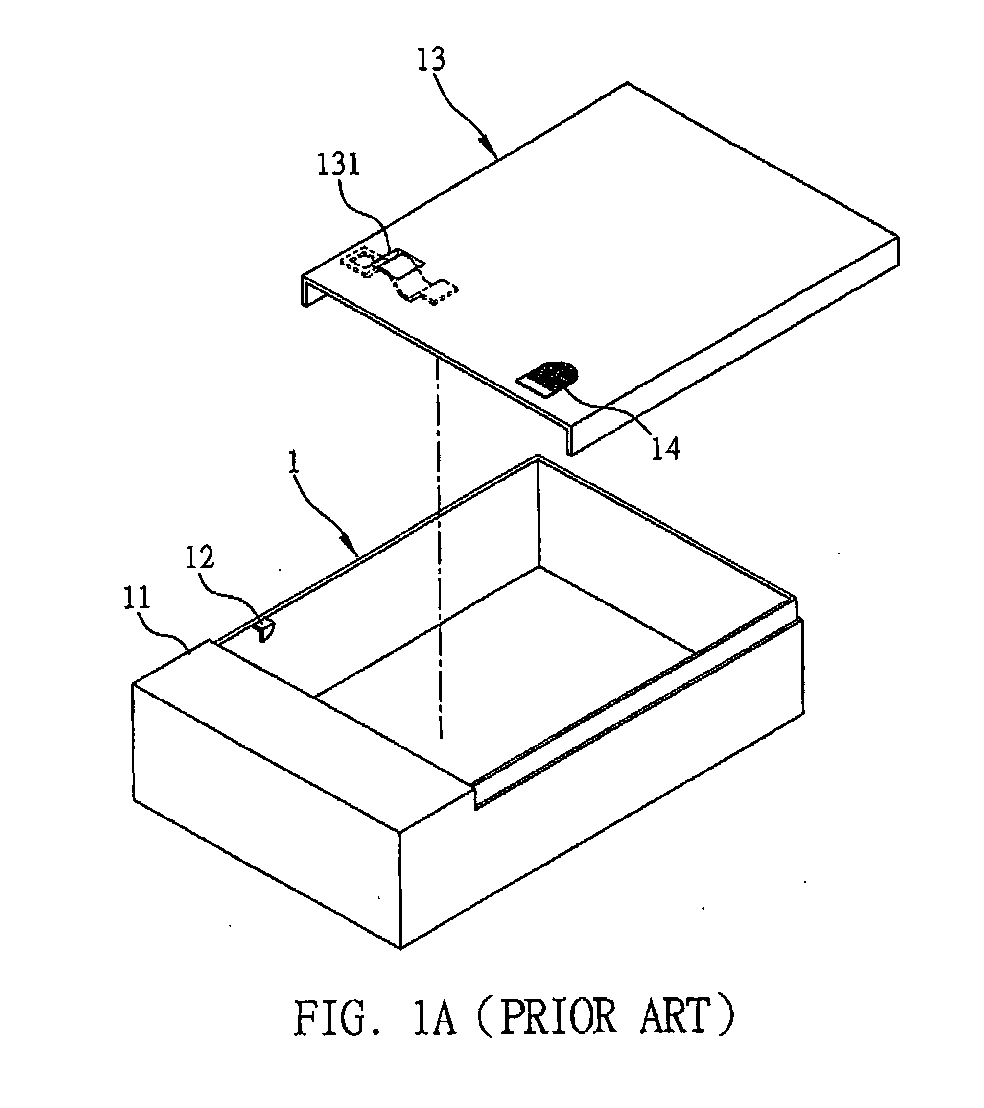
For an old time cage server, mostly a lid body is placed on the top of the housing of the cage server and make sure that a plurality of holes of the lid body is aiming at a plurality of corresponding holes of the cage server, and then apply a plurality of screws to secure the lid body to the cage server, because the lid body of the cage server has a great deal of volume and weight, to aim at the holes for screwing and securing is not an easy job for the assemblers, thus the f performance efficiency is not impressive; besides, the plurality of holes and the plurality of screws raises the production cost too.
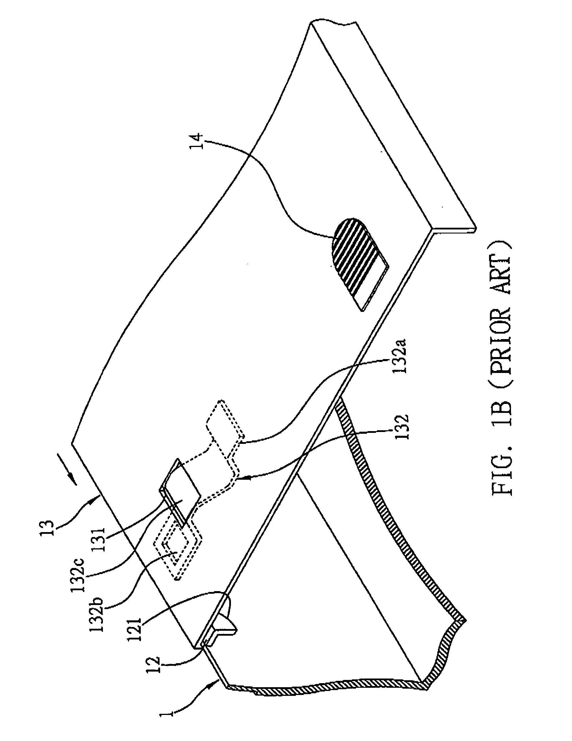
The above-mentioned fixing mechanism does not have the disadvantages of requiring using screws and tools, however, to detach the lid body 13, one must push down on the pressing portion 132c of the elastic chip 132, and meanwhile put force outward on the push portion 14, which is very energy consuming, furthermore, the improper coordination of any extra press down force and the outward push movement may cause damage to the elastic chip 132 and the hook unit 12, and it is very inconvenient.
Hence, it is a highly urgent issue in the industry for how to provide a lid body fixing mechanism to effectively solve the drawbacks of the prior art as mentioned above.

Method used


Image

  • Lid body anchor system
  • Lid body anchor system
  • Lid body anchor system

Examples


Embodiment Construction

[0026]The following illustrative embodiments are provided to illustrate the disclosure of the present invention, these and other advantages and effects can be apparently understood by those in the art after reading the disclosure of this specification. The present invention can also be performed or applied by other different embodiments.

[0027]The details of the specification may be on the basis of different points and applications, and numerous modifications and variations can be devised without departing from the spirit of the present invention.

[0028]Referring to FIG. 2A, which is an explosive view of a lid body fixing mechanism according to the present invention, a front cover 21 is fixed to a mechanical housing 2 and has location and size corresponding to those of a lid body 3. After fixed to the mechanical housing 2, the lid body 3 props against the front cover 21, to seal the mechanical housing 2 completely. A blocking unit 221 such as a pillar is installed on an inner wall 22 ...


PUM


Abstract

A lid body fixing mechanism is disclosed to fix a lid body that seals an opening of a mechanical housing. The lid body has a through hole. The lid body fixing mechanism includes a blocking unit installed on an inner side of the mechanical housing and corresponding to the through hole, an operation unit installed in the through hole and pivotally connected to the lid body, and an elastic unit installed in an inner wall of the lid body. The operation unit has an operation end, a propping end, and a hook portion located on the operation end for positioning at the blocking unit. By lifting the operation unit, the hook portion is departed from the blocking unit. The elastic unit has a supporting portion protruding into the through hole and supporting the propping end, for bouncing the lifted operation unit back to an initial position.

Description

BACKGROUND OF THE INVENTION[0001]1. Field of the Invention[0002]This invention relates generally to lid body fixing mechanisms, and more specifically, to a lid body fixing mechanism that provides an easy operation of attaching and detaching a lid body.[0003]2. Description of Related Art[0004]Accordingly, with the fast pace of technology nowadays, the computer processing speed is getting faster and faster, and the price is also getting lower. Therefore, the application scope of the technology has been widen greatly, such as enterprise servers or personal desktop computers, take the server as an example, a server can operate independently and be a swappable computer system, the server can be integrated inside a cage and becomes a stacked serial cage server, the mechanical housing of a cage server is commonly made out metals, and usually it is huge and heavy. For an old time cage server, mostly a lid body is placed on the top of the housing of the cage server and make sure that a plura...

Claims


Application Information

Patent Timeline
Patent Type & Authority Applications(United States)
IPC IPC(8): E05C19/06E05C19/10E05C3/00
CPCG06F1/181E05B65/006Y10T292/0825Y10T292/0813Y10T292/1062
Inventor SUNG, TZU-WEN
Owner INVENTEC CORP
Learn More